LDO circuit based on FVF control

A technology for controlling circuits and circuits, applied in control/regulating systems, regulating electrical variables, instruments, etc., can solve the problem of low load transient response capability of LDO circuits, low power consumption, large load current and high power supply suppression ratio transient. to achieve the effect of low power consumption, high power supply rejection ratio, and large load current

Pending Publication Date: 2018-01-05
FOSHAN UNIVERSITY
View PDF5 Cites 12 Cited by
  • Summary
  • Abstract
  • Description
  • Claims
  • Application Information

AI Technical Summary

Problems solved by technology

The LDO circuit with this structure has the problem of low load transient response capability
However, with the continuous development of integrated circuits, the traditional LDO structure can no longer meet the requirements of low power consumption, large load current, high power supply rejection ratio, and good transient response. Therefore, it is urgent to design a new circuit

Method used


Image

  • LDO circuit based on FVF control
  • LDO circuit based on FVF control
  • LDO circuit based on FVF control

Examples


Embodiment 1

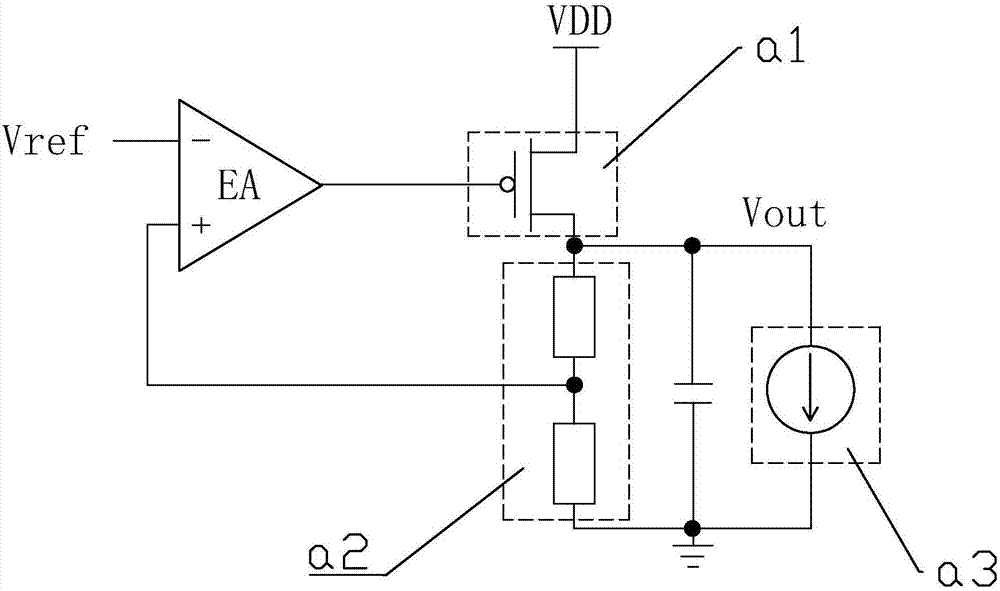
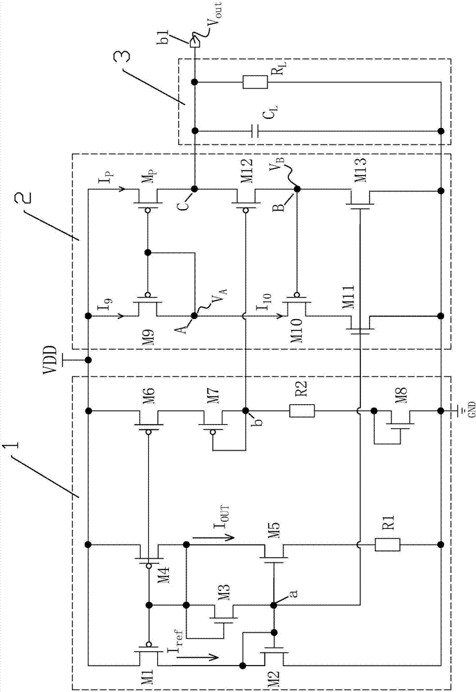
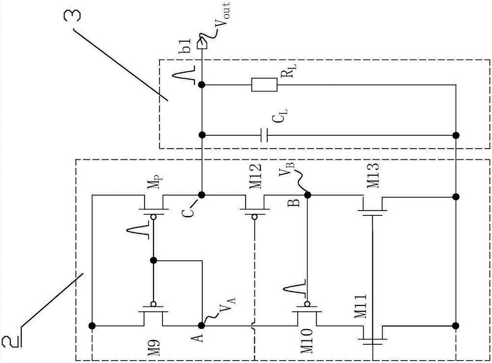
[0015] Embodiment 1, reference figure 2 , an LDO circuit based on FVF control, comprising: a bias circuit, an FVF control circuit, and a load circuit;

[0016] The bias circuit is composed of: PMOS transistors M1, M4, M6, M7, NMOS transistors M2, M5, M8, resistors R1, R2, the gate of the M1 is respectively connected to the gates of the M4, M6, so The drain of the M1 is connected to the drain of the M2, the gate, the drain of the M2, and the gate of the M5 are collectively connected to the first bias output node a, and the drain of the M5 is connected to the M4 The drain of the M5 is connected to one end of the R1, the drain of the M6 ​​is connected to the source of the M7, the gate, the drain of the M7, and one end of the R2 are collectively connected At the second bias output node b, the other end of R2 is respectively connected to the gate and drain of M8, the sources of M2 and M8, and the other end of R1 are respectively connected to the ground GND, and the M1, The sourc...


PUM


Abstract

The invention discloses an LDO circuit based on FVF control. The LDO circuit is characterized by comprising a biasing circuit, an FVF control circuit and a load circuit. The created circuit structureadopts the FVF control circuit as a core. Compared with an existing LDO circuit, the LDO circuit has good parameter indexes such as low power consumption, large load current, a high power supply rejection ratio and transient response, and meets the development requirement of the LDO circuit in the future. The circuit structure can be widely applied to an SoC.

Description

technical field [0001] The invention relates to a system for adjusting electric or magnetic variables, in particular to an LDO (Low Dropout Regulator, LDO, low dropout linear regulator) circuit. Background technique [0002] Almost all electronic circuits require a stable voltage source that is maintained within certain tolerances for proper operation (a typical CPU circuit only allows the voltage source to deviate from the rated voltage by no more than ±3% maximum). This fixed voltage is provided by some kind of voltage regulator. The LDO circuit is one of the regulators. [0003] Such as figure 1 As shown, the traditional LDO circuit includes: reference voltage Vref, error amplifier EA, power tube a1, resistor divider a2, and current source a3. The LDO circuit automatically detects the output voltage Vout through the resistor divider a2, and the error amplifier EA constantly adjusts the current source a3 so as to maintain the output voltage Vout at the rated voltage. T...

Claims


Application Information

Patent Timeline
Patent Type & Authority Applications(China)
IPC IPC(8): G05F3/26
Inventor 段志奎王志敏樊耘于昕梅陈建文李学夔王兴波朱珍王东
Owner FOSHAN UNIVERSITY
Why Eureka
Try Eureka