Storage battery electrode plate packaging machine

A technology of plate-cladding machine and storage battery, which is applied in secondary battery manufacturing, sustainable manufacturing/processing, climate sustainability, etc. Highly flexible effect

Pending Publication Date: 2018-01-05
ZHONGSHAN SHENGYI ELECTRIC MACHINERY CO LTD
View PDF0 Cites 4 Cited by
  • Summary
  • Abstract
  • Description
  • Claims
  • Application Information

AI Technical Summary

Problems solved by technology

The components connected by plates with the same polarity are called pole groups. Pole groups are made by alternately separating the positive and negative plates through separator paper. It is done by manual operation, not only the processing efficiency is very low, but also because the electrode plate is generally made of lead material, it is easy to generate heavy metal dust during the processing process, which is not conducive to the health of personnel. Therefore, based on the consideration of safe production in the relevant national regulations, manufacturers are required to Automatic wrapping machines are used for plate processing, so there are various wrapping machines on the market, but the wrapping machines currently on the market are basically fixed specifications, which cannot be applied to the production of batteries of various sizes. The applicant has developed a cladding machine suitable for the production of various types of batteries
[0003] However, the current wrapping machines are all of fixed specifications, that is, they can only be used to produce battery plate groups of one specification. When the size of the plates changes, it is necessary to reconfigure the wrapping machine, which increases the production cost.

Method used


Image

  • Storage battery electrode plate packaging machine
  • Storage battery electrode plate packaging machine
  • Storage battery electrode plate packaging machine

Examples


Embodiment Construction

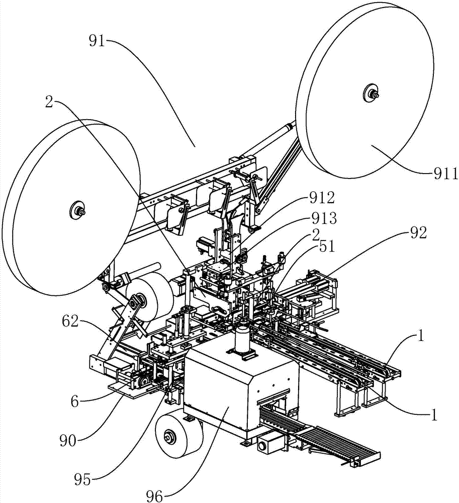
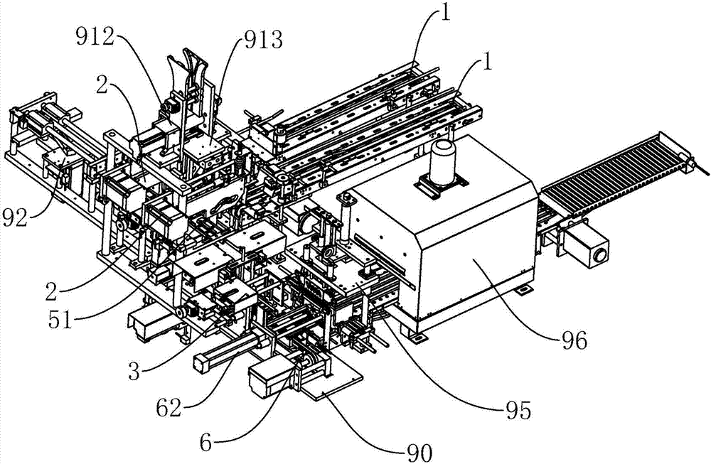
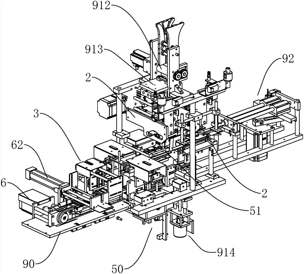
[0054] refer to Figure 1 to Figure 30 , Figure 1 to Figure 30 It is a structural schematic diagram of a specific embodiment of the present invention. As shown in the figure, the battery wrapping machine includes: a frame 90 , a plate stacking mechanism, a plate feeding mechanism, a plate pushing mechanism 92 , and an output channel device 6 .

[0055] refer to Figure 6 to Figure 9 The stacking mechanism is arranged on the frame 90, which includes a stacking channel 51, a loading bin device, and a sinking device 50, and the stacking channel 51 is provided with a first blanking position 5a and a second blanking position 5b , between the first blanking position 5a and the second blanking position 5b, a wrapping paper channel 54 is arranged, the carrying bin device is arranged below the second blanking position 5b, and the sinking device 50 is arranged in the carrying bin Below the device, and the first blanking position 5a is connected to the loading bin device.

[0056] Th...


PUM


Abstract

The invention discloses a storage battery electrode plate packaging machine. The storage battery electrode plate packaging machine comprises a rack, a plate laminating mechanism, a plate conveying mechanism, a plate pushing mechanism and an output channel apparatus; the plate conveying mechanism can convey the electrode plate to the plate laminating mechanism; then the electrode plate is pushed bythe plate pushing mechanism to complete procedures of paper packaging and plate laminating; the laminated plate group after plate laminating is completed is sent out through the output channel apparatus; a laminated plate channel distance adjustment apparatus is arranged on a laminated plate channel of the plate laminating mechanism, so that the width of the laminated plate channel can be adjusted according to the specification of the electrode plate; and an electrode plate conveying apparatus of the plate conveying mechanism has a height adjustment apparatus, so that the height of the outletof the conveying channel can be adjusted according to the specification of the electrode plate. By adoption of the storage battery electrode plate packaging machine, conveying and plate laminating ofelectrode plates of different specifications can be satisfied, production of batteries of different specifications can be satisfied, and high use flexibility and wider application range can be realized.

Description

technical field [0001] The invention relates to the field of battery production equipment, in particular to a battery wrapping machine. Background technique [0002] During the processing of the storage battery, the pole plate is an important component. With the development of the production process of the battery, in the existing processing process, in order to increase the capacity of the battery and make the structure compact, the electrodes can be composed of parallel connection of the pole plates. The components connected by plates with the same polarity are called pole groups. Pole groups are made by alternately separating the positive and negative plates through separator paper. It is done by manual operation, not only the processing efficiency is very low, but also because the electrode plate is generally made of lead material, it is easy to generate heavy metal dust during the processing process, which is not conducive to the health of personnel. Therefore, based on...

Claims


Application Information

Patent Timeline
Patent Type & Authority Applications(China)
IPC IPC(8): H01M10/04
CPCY02E60/10Y02P70/50
Inventor 黄志清周波陈水生
Owner ZHONGSHAN SHENGYI ELECTRIC MACHINERY CO LTD
Why Eureka
Try Eureka