Supercharge Your Innovation With Domain-Expert AI Agents!

Intelligent dust removing device

A technology for dust removal equipment and control modules, which is applied in chemical instruments and methods, dispersed particle separation, combined devices, etc., can solve the problems of high cost and general dust removal effect, and achieve the effect of simple structure, avoiding excessive water vapor, and reducing costs.

Inactive Publication Date: 2018-01-09
太仓市除尘设备厂
View PDF5 Cites 0 Cited by
  • Summary
  • Abstract
  • Description
  • Claims
  • Application Information

AI Technical Summary

Problems solved by technology

[0003] Most of the existing dust removal equipment on the market use fans or electrostatic dust collectors. During the working process, the dust removal effect is average, and the discharged gas will still be mixed with a lot of particles, and some large-scale dust removal equipment has the best dust removal effect in time. Very good, but its cost is high, so the existing dust removal equipment needs to be improved

Method used


Image

  • Intelligent dust removing device
  • Intelligent dust removing device

Examples


Embodiment 1

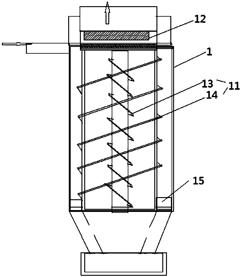
[0022] As shown in the figure, an intelligent dust removal equipment includes: a housing 1 and a control device 2, the housing 1 is provided with a set of air inlets and an air outlet, and the housing 1 is provided with a rotating mechanism 11 and the first filtering mechanism 12, the rotating mechanism 11 is provided with an inner rotating mechanism 13 and an outer rotating mechanism 14, the inner rotating mechanism 13 and the outer rotating mechanism 14 are arranged in opposite directions, and the first filtering mechanism 12 is provided with At the outlet of the inner rotating mechanism 13 , both the rotating mechanism 11 and the first filtering mechanism 12 are connected to the control device 2 .

[0023] In this embodiment, a second filter mechanism 15 is provided at the connection between the outer rotation mechanism 14 and the inner rotation mechanism 13 , and the second filter mechanism 15 is connected to the control device 2 .

[0024] In this embodiment, the first fi...

Embodiment 2

[0030] As shown in the figure, an intelligent dust removal equipment includes: a housing 1 and a control device 2, the housing 1 is provided with a set of air inlets and an air outlet, and the housing 1 is provided with a rotating mechanism 11 and the first filtering mechanism 12, the rotating mechanism 11 is provided with an inner rotating mechanism 13 and an outer rotating mechanism 14, the inner rotating mechanism 13 and the outer rotating mechanism 14 are arranged in opposite directions, and the first filtering mechanism 12 is provided with At the outlet of the inner rotating mechanism 13 , both the rotating mechanism 11 and the first filtering mechanism 12 are connected to the control device 2 .

[0031] In this embodiment, a second filter mechanism 15 is provided at the connection between the outer rotation mechanism 14 and the inner rotation mechanism 13 , and the second filter mechanism 15 is connected to the control device 2 .

[0032] In this embodiment, the first fi...


PUM


Abstract

The invention discloses an intelligent dust removing device which comprises a housing and a control device, wherein a group of air inlets and an air outlet are formed in the housing; a rotating mechanism and a first filtering mechanism are arranged inside the housing; an inner rotating mechanism and an outer rotating mechanism are arranged in the rotating mechanism; the inner rotating mechanism and the outer rotating mechanism are arranged in opposite directions; an exit for the inner rotating mechanism is formed in the first filtering mechanism; and both the rotating mechanism and the first filtering mechanism are connected with a control device. In the dust removing device disclosed by the invention, the inner rotating mechanism and the outer rotating mechanism are arranged in the housing, so that outer vortexes and inner vortexes are formed, double separation can be achieved by utilizing natural gravity, then deep filtration is performed through the filtering mechanism, and furtherthe filtering effect is greatly improved; and the device is simple in entire structure, easy to implement, and capable of effectively reducing the cost.

Description

technical field [0001] The invention belongs to the field of dust removal equipment, in particular to an intelligent dust removal equipment. Background technique [0002] With the rapid development of social economy, people's living standards and quality of life are constantly improving, and whether it is production or life, people's rhythm is constantly accelerating, and most of them have realized intelligence and automation in both production and life. , and the quality requirements for the environment are getting higher and higher, which promotes the generation of dust removal equipment. [0003] Most of the existing dust removal equipment on the market use fans or electrostatic dust collectors. During the working process, the dust removal effect is average, and the discharged gas will still be mixed with a lot of particles, and some large-scale dust removal equipment has the best dust removal effect in time. Very good, but its cost is relatively high, so the existing du...

Claims


Application Information

Patent Timeline
Patent Type & Authority Applications(China)
IPC IPC(8): B01D50/00
Inventor 陆维光
Owner 太仓市除尘设备厂
Features
  • R&D
  • Intellectual Property
  • Life Sciences
  • Materials
  • Tech Scout
  • Unparalleled Data Quality
  • Higher Quality Content
  • 60% Fewer Hallucinations
Learn More