Shift cable noise reduction device

A shift cable and noise reduction technology, which is applied in the direction of transmission control, shaft and bearing, linear motion shaft, etc., can solve the problem of no noise reduction effect, achieve noise reduction processing, and realize the effect of noise

Active Publication Date: 2019-10-11
GREAT WALL MOTOR CO LTD
View PDF6 Cites 0 Cited by
  • Summary
  • Abstract
  • Description
  • Claims
  • Application Information

AI Technical Summary

Problems solved by technology

The gear shift cable is the main transmission path of transmission noise. Usually, a mass block is added or a sleeve is placed on the cable, and structures such as thin slices are added to the circumference of the sleeve to achieve noise and vibration attenuation, but no good noise is produced. noise reduction effect

Method used


Image

  • Shift cable noise reduction device
  • Shift cable noise reduction device
  • Shift cable noise reduction device

Examples


Embodiment 1

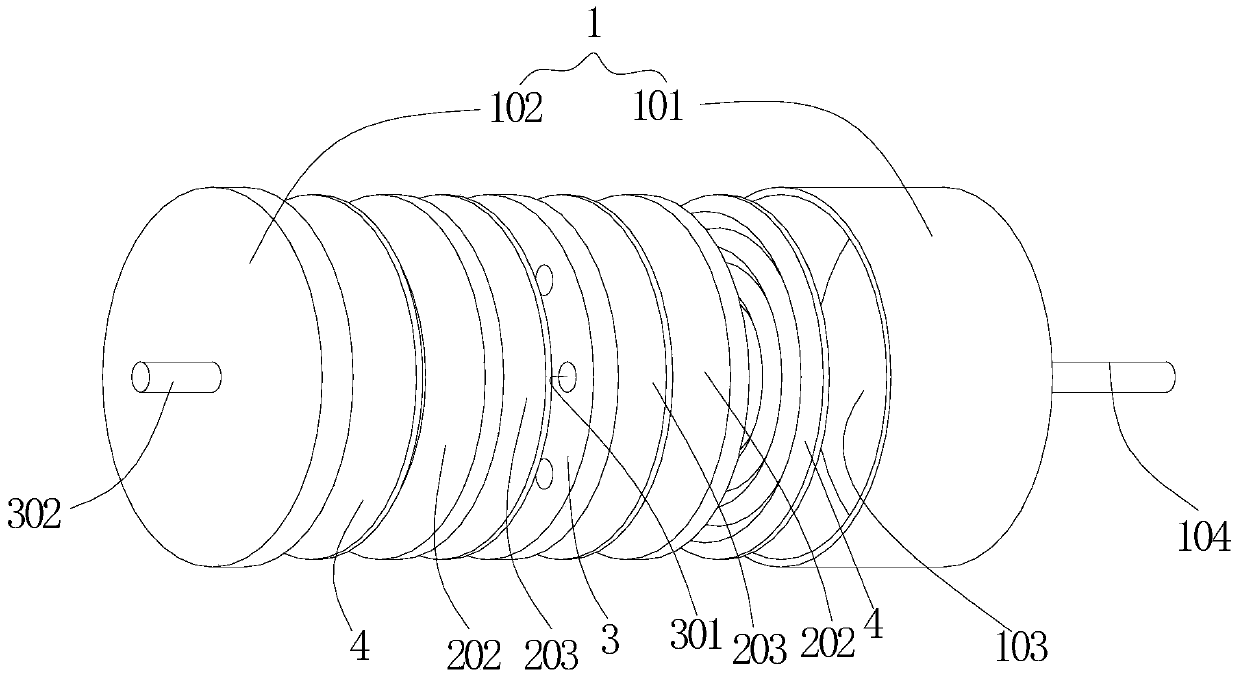
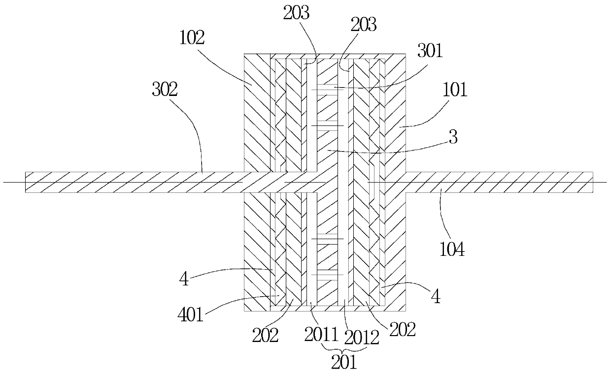
[0034] This embodiment relates to a gear shift cable noise reduction device, the overall structure of which includes a housing with an accommodating cavity formed therein, a sealing part, a sliding part, a first connecting part and a second connecting part. Depend on figure 1 and figure 2 It can be seen that the housing 1 has a cylindrical shape as a whole, and it is composed of a main body 101 with a U-shaped axial cross-section and a cover 102 fixedly connected to the opening of the main body 101 by a cover buckle. The hollow interior of the main body 101 is An accommodating cavity 103 is formed. In subject 101, with figure 1 On the right side end surface of the state shown, there is a first connecting part 104 fixedly connected, the first connecting part 104 is rod-shaped, and in order to improve the overall use effect, the axis of the first connecting part 104 coincides with the center line of the housing 1 . The first connecting portion 104 is used to be fixedly conn...

Embodiment 2

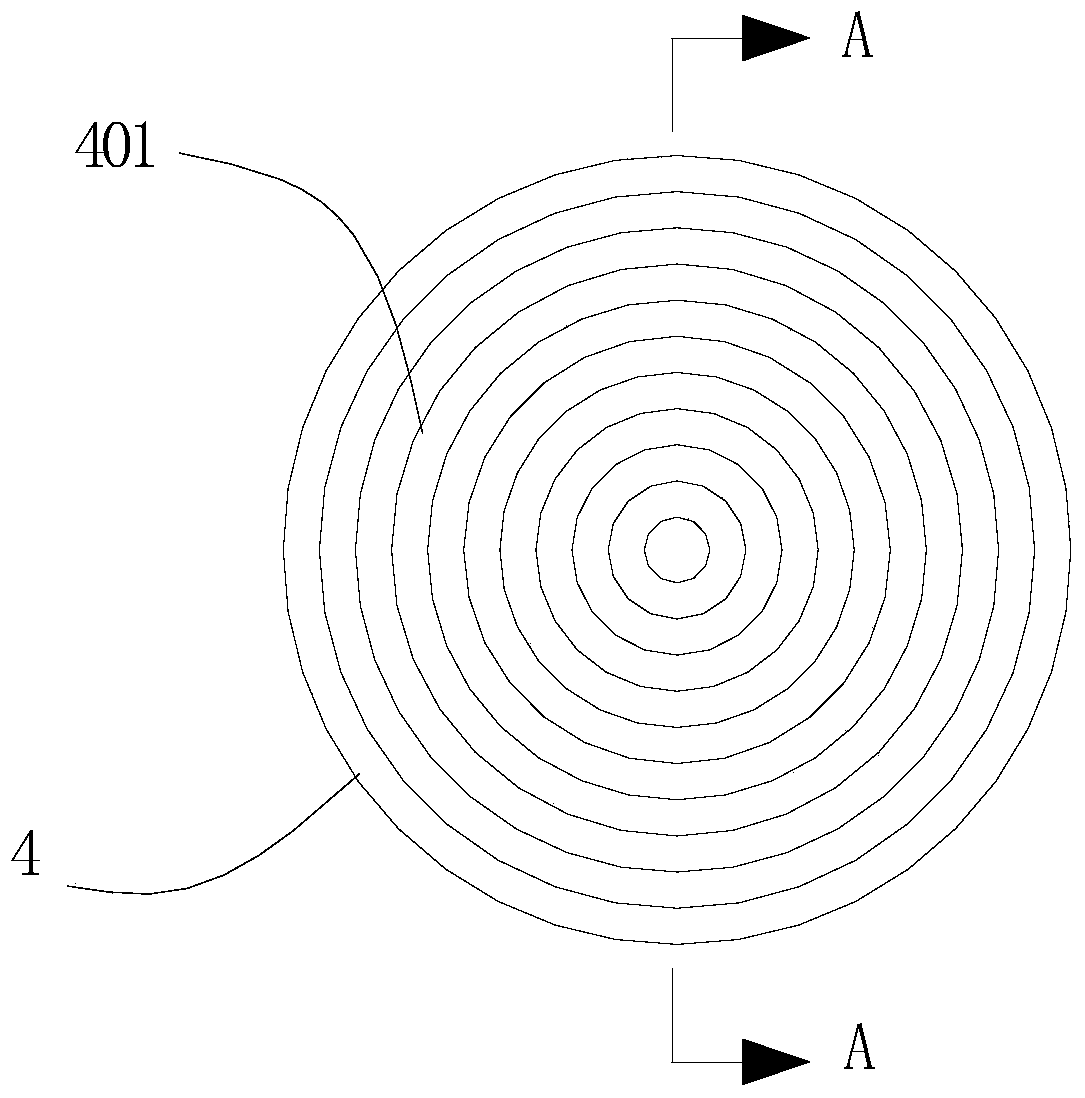
[0043] This embodiment also relates to a shift cable noise reduction device, which is basically the same as Embodiment 1, except that, on the support portion 4, a secondary support portion 402 facing the isolation plate 202 is formed; Figure 5 so Figure 4 The state shown shows a schematic structural view of the support part 4. It can be seen that the axial length of the secondary support part 402 is smaller than the axial length of the primary support part 401, that is, the secondary support part 402 is also an annular sawtooth In this way, based on the description of the first embodiment, when the excitation is large, after the isolation plate 202 compresses the primary support portion 401, it can continue to compress the secondary support portion 401. The first-level support part 402 is formed to be squeezed sequentially. In order to better improve the noise reduction effect, the saw-tooth gap of the second-level support part 402 is smaller than the saw-tooth gap on the fi...

Embodiment 3

[0045] This embodiment also relates to a gear shift cable noise reduction device, which is basically the same as Embodiment 1, the difference is that the Figure 6 As can be seen from the illustration, the setting of the support part 4 is canceled in this embodiment, and the noise reduction effect is achieved only through the gas in the sealed cavity 201 , which can produce a better noise reduction effect on high-frequency noise excitation.

[0046] It is worth noting that, by Figure 6 It can be seen that the sealed cavity 201 can not only be formed by two isolation plates 202 spaced apart, but also the two isolation plates can be discarded, and the accommodating cavity can be directly used as the sealed cavity. In addition, in Embodiment 1, the sealing part may also be a separate component arranged in the accommodating cavity, such as adopting a box structure, etc., which may not cooperate with the inner wall of the housing 1 .


PUM


Abstract

The invention relates to a gear shifting inhaul cable noise reduction device which comprises a shell, a sealed part, a sliding part and a second connection part. A containing cavity is formed in the shell, and the end, in the axial direction, of the shell is fixedly connected with a first connection part. The sealed part is arranged in the containing cavity, and a sealed cavity filled with gas isformed in the sealed part. The sliding part is arranged in the sealed cavity so that the sealed cavity can be divided in the axial direction of the shell, and can slide in the axial direction of the shell, and through communicating holes are formed in the sliding part. The second connection part extends from the outer portion of the side, opposite to the first connection part, of the shell into the sealed cavity and is fixedly connected with the sliding part. By arranging the sealed part, when noise of a transmission is transferred through a gear shifting inhaul cable, the sliding part slidesin the sealed cavity due to the fact that the first connection part and the second connection part are connected with the inhaul cable, gas flows between the portions, on the two sides of the slidingpart, of the sealed cavity through the communicating holes, and then, noise reduction treatment on the noise is achieved.

Description

technical field [0001] The invention relates to the technical field of vehicle noise treatment, in particular to a gear shift cable noise reduction device for noise reduction processing of the noise generated by a vehicle transmission. Background technique [0002] Transmission noise usually includes whistling and tooth knocking. Whistle is mainly produced by slapping, friction and extrusion of liquid between tooth surfaces, mainly reflected in the fundamental frequency of meshing, and the frequency range is generally 300-3000Hz; Produced by the mutual knocking between gears, it is mainly reflected in the meshing harmonic frequency, and the frequency range is generally 2000-5000Hz, or even higher. Transmission noise has a large frequency range and contains medium and high frequency components at the same time. Therefore, the control of medium frequency noise and high frequency noise is the main means of reducing transmission noise. [0003] The NVH performance control mecha...

Claims


Application Information

Patent Timeline
Patent Type & Authority Patents(China)
IPC IPC(8): F16C1/20F16C1/26F16H59/02
Inventor 靳豹石宇鹏刘二宝陈岳昌孙飞王豹敬杰张浩
Owner GREAT WALL MOTOR CO LTD
Why Eureka
Try Eureka