Ship kitchen steam elimination device and working method

A steam and kitchen technology, which is applied in the field of ship galley steam elimination device and marine galley steam elimination device, can solve the problems of increased humidity in the room, waste of heat energy and fresh water resources, blurred vision of personnel, etc., and achieves remarkable effects and energy saving effects

Pending Publication Date: 2018-01-09
JIANGSU UNIV OF SCI & TECH
View PDF8 Cites 6 Cited by
  • Summary
  • Abstract
  • Description
  • Claims
  • Application Information

AI Technical Summary

Problems solved by technology

[0008] The purpose of the present invention is to provide a ship galley steam elimination device and working method for the blurred vision of personnel caused by a large amount of steam generated in the kitchen, the increase of humidity in the room, and the waste of heat energy and fresh water resources. Obvious, and can effectively recycle waste heat and fresh water resources

Method used


Image

  • Ship kitchen steam elimination device and working method
  • Ship kitchen steam elimination device and working method

Examples


Embodiment 1

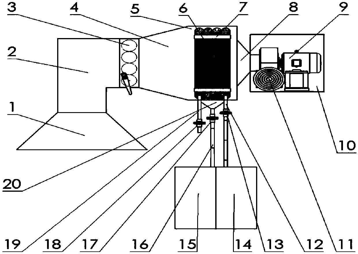
[0030] like figure 1 Shown: a steam elimination device for a ship galley, including a steam suction section, a condensation section and a discharge section. The steam suction section includes a suction reducer 1, a right-angle elbow 2, a damper 3, and a diffuser connected in sequence. 4. The condensing section includes a straight pipe 5 connected and sealed to the outlet end of the expander pipe 4 and a finned radiator 6 installed in the straight pipe 5 through a fixing frame 7. The finned radiator The outlet of the device 6 communicates with the first water tank 14 arranged below the straight pipe 5 through the first water pipe 12 equipped with the first valve 13, and the inlet of the finned radiator 6 passes through the first water pipe 12 equipped with the third valve 18. The three water pipes 19 communicate with the cold water supply end, and the bottom of the straight pipe 5 is provided with a conical collector 20, and the bottom of the conical collector 20 is connected w...

Embodiment 2

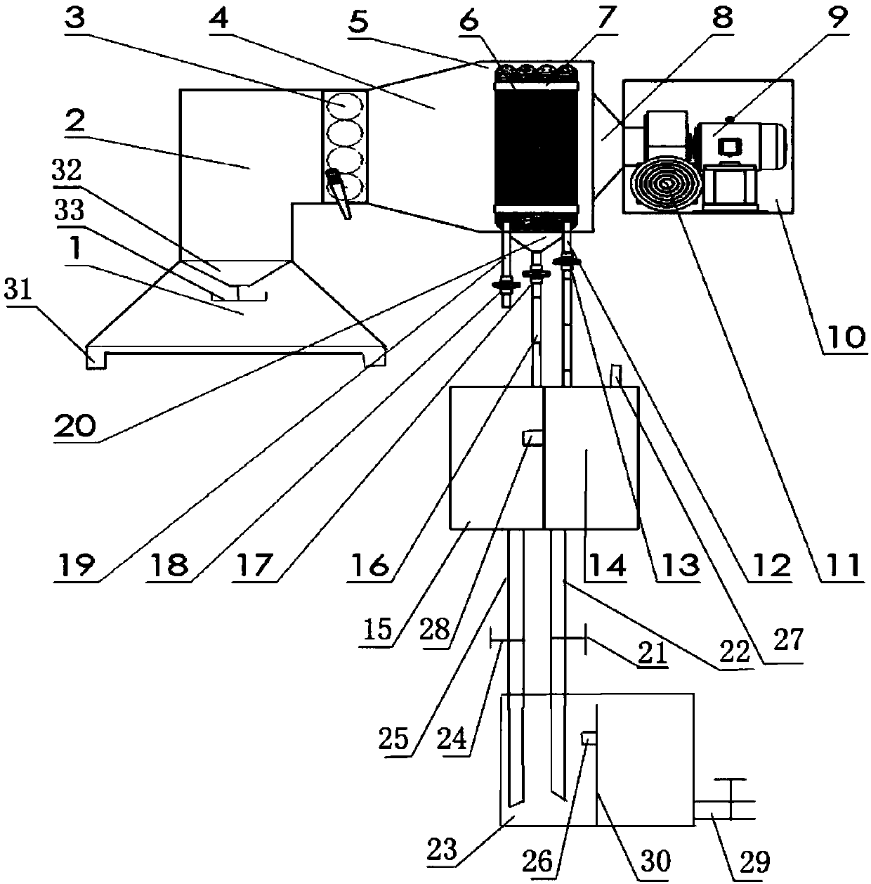
[0032] like figure 2 Shown: a steam elimination device for a ship galley, including a steam suction section, a condensation section and a discharge section. The steam suction section includes a suction reducer 1, a right-angle elbow 2, a damper 3, and a diffuser connected in sequence. 4. The condensing section includes a straight pipe 5 connected and sealed to the outlet end of the expander pipe 4 and a finned radiator 6 installed in the straight pipe 5 through a fixing frame 7. The finned radiator The outlet of the device 6 communicates with the first water tank 14 arranged below the straight pipe 5 through the first water pipe 12 equipped with the first valve 13, and the inlet of the finned radiator 6 passes through the first water pipe 12 equipped with the third valve 18. The three water pipes 19 communicate with the cold water supply end, and the bottom of the straight pipe 5 is provided with a conical collector 20, and the bottom of the conical collector 20 is connected ...


PUM


Abstract

The invention provides a ship kitchen steam elimination device. The ship kitchen steam elimination device comprises a steam suction section, a condensation section and an exhaust section. The steam suction section comprises a suction inlet reducing pipe, a righted-angle elbow pipe, an air valve and a diverging pipe. The condensation section comprises a straight pipe and a finned radiator fixed into the straight pipe. The exhaust section comprises a centrifugal fan with an exhaust inlet connected with the straight pipe through a transition pipe. The exterior of the centrifugal fan is provided with a fan decorative box with an air diffuser. The air diffuser is located at an air outlet of the centrifugal fan. The ship kitchen steam elimination device is remarkable in steam elimination effect,besides waste heat in steam can be recycled, and meanwhile fresh water is produced; and the ship kitchen steam elimination device is suitable for kitchen steam elimination of ships and ocean platforms with steamer equipment and also suitable for steam elimination of other occasions such as engine rooms.

Description

technical field [0001] The invention relates to a ship galley steam elimination device and a working method, which is a ship galley steam elimination device which uses a centrifugal fan as forced power and rationally utilizes steam waste heat, and belongs to the technical field of kitchen equipment. Background technique [0002] In the process of steaming buns, rice and steamed buns, a certain amount of water will be added to the steamer equipment in the ship galley, and then the power supply will be turned on for heating. A large amount of water vapor will be generated after the water boils, and the heat contained in the water vapor is mainly divided into two parts, the first part is sensible heat, that is, the heat in the water vapor itself and the heat carried by a part of the air; the second part is sensible heat. The second part is latent heat, which is the heat released when water vapor liquefies. If this heat is not recycled, it will be wasted. At the same time, if ...

Claims


Application Information

Patent Timeline
Patent Type & Authority Applications(China)
IPC IPC(8): F28B1/02F28B9/08F28B11/00B63B29/22B63J1/00B01D5/00
Inventor 冯国增徐新帆
Owner JIANGSU UNIV OF SCI & TECH
Why Eureka
Try Eureka