Laser-tracker-based calibration method for six-degree-of-freedom robot tool coordinate system

A technology of tool coordinate system and laser tracker, which is applied in the field of six-degree-of-freedom industrial robots, can solve the problems of complex operation and low precision, and achieve the effects of simple operation, high precision, data processing and intuitive results

Inactive Publication Date: 2018-01-09
ANHUI LEADING PRECISION TECH
View PDF4 Cites 25 Cited by
  • Summary
  • Abstract
  • Description
  • Claims
  • Application Information

AI Technical Summary

Problems solved by technology

[0003] At present, there are many ways to calibrate the tool coordinate system of industrial robots, such as using triggers to calibrate, using four poi

Method used


Image

  • Laser-tracker-based calibration method for six-degree-of-freedom robot tool coordinate system
  • Laser-tracker-based calibration method for six-degree-of-freedom robot tool coordinate system
  • Laser-tracker-based calibration method for six-degree-of-freedom robot tool coordinate system

Examples


Embodiment Construction

[0033] The calibration method of the six-degree-of-freedom robot tool coordinate system based on the laser tracker of the present invention will be further described in detail below in conjunction with the accompanying drawings and specific embodiments:

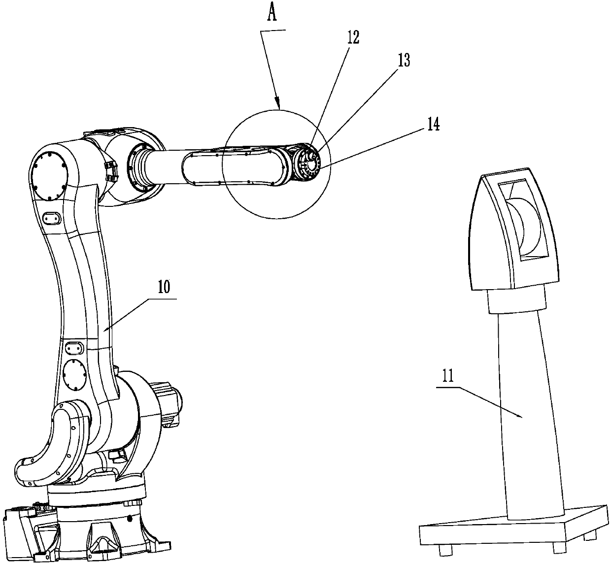
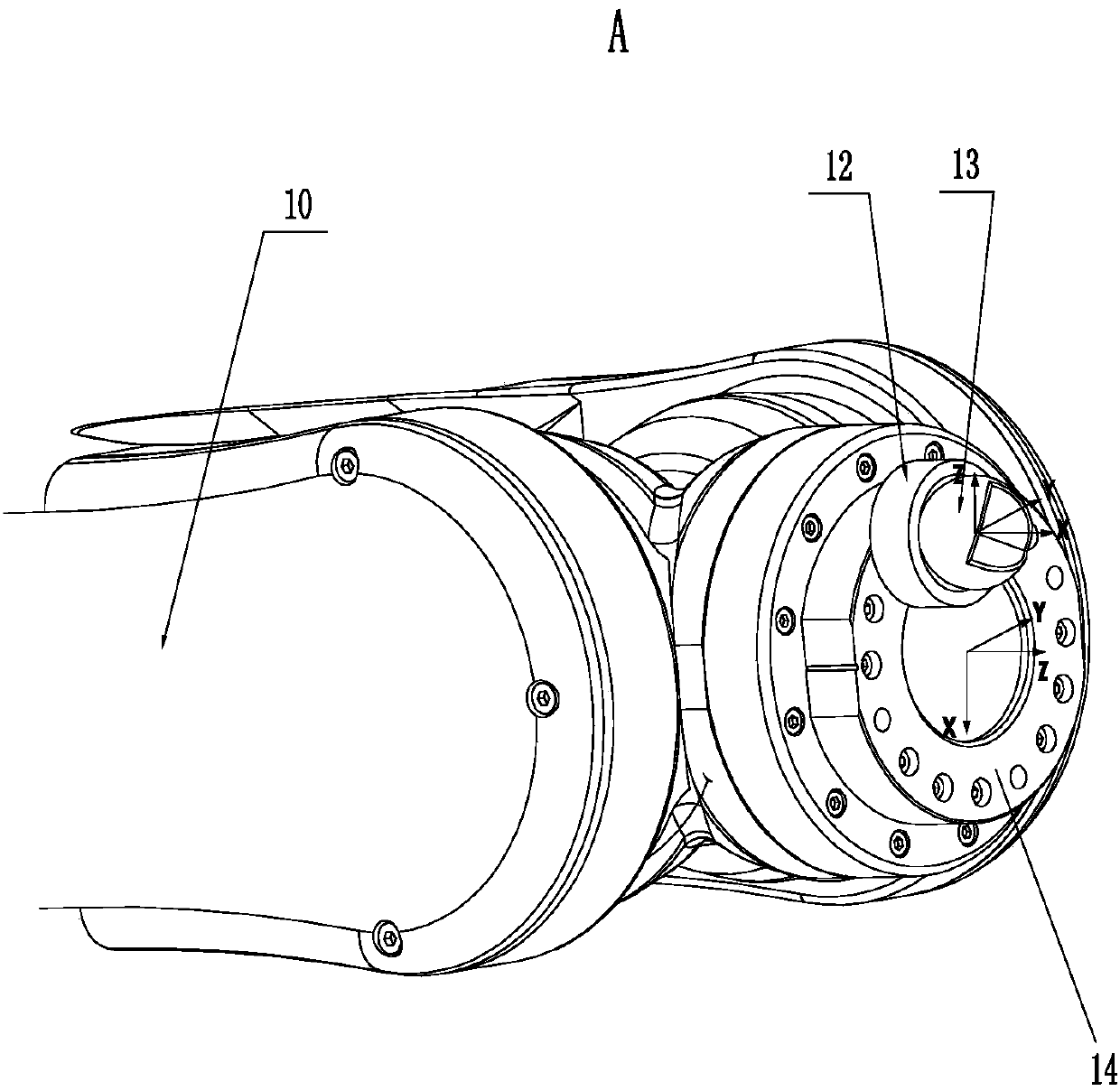
[0034] Such as figure 1 with figure 2 As shown, in this specific embodiment, the calibration method of the six-degree-of-freedom robot tool coordinate system based on the laser tracker of the present invention includes the following steps:

[0035] (1) Place the laser tracker 11 at 3 meters directly in front of the robot body 10, and preheat it in advance;

[0036] (2) fixedly install the target ball base 12 and the target ball 13 on the flange 14 at the end of the robot body 10;

[0037] (3) run SA (Spatial Analyzer) software and connect laser tracker 11;

[0038] (4) adjust the robot body 10 to the non-singular point position near the zero position, and record the spatial position of the target ball 13 under this postur...


PUM


Abstract

The invention relates to a laser-tracker-based calibration method for a six-degree-of-freedom robot tool coordinate system. The method comprises: a laser tracker is arranged in front of a robot body at a distance of three meters; a pedestal and a target ball are fixedly installed on a flange plate; SA software is operated and a laser tracker is connected; the robot body is adjusted to be at a non-singular point position and a spatial position of the target ball at an attitude is recorded; the center of the flange plate is kept to be unchanged, the attitude of the flange plate is changed step by step and all attitude positions are recorded, the operation is repeated by 19 times to obtain spatial positions with serial numbers P1 to P20 at 20 attitudes; ball fitting is carried out on the twenty spatial position points by the SA software to obtain a sphere with the center of the flange plate as a centre of sphere; at an attitude Pi, a flange coordinate system {Tool000} is established; andunder the {Tool000} coordinate system, the Pi coordinate expresses a positional relationship between a tool and the flange coordinate system, and a tool coordinate system is determined based on the coordinate system positional relationship. According to the invention, the operation is simple and the calibration accuracy is high.

Description

technical field [0001] The invention relates to the technical field of six-degree-of-freedom industrial robots, in particular to a method for calibrating a six-degree-of-freedom robot tool coordinate system based on a laser tracker. Background technique [0002] With the development of industry, industrial robots are used more and more widely. In practical applications, most robots complete various tasks by installing different operating tools at the end. In order to achieve the high-precision requirements of the robot, before using it, it is necessary to establish the positional relationship of the tip of the robot tool relative to the flange at the end of the robot, that is, to calibrate the tool coordinate system of the robot. [0003] At present, there are many methods to calibrate the tool coordinate system of industrial robots, such as using triggers to calibrate, using four points to calculate the center of the sphere, etc., but these methods are more complicated to o...

Claims


Application Information

Patent Timeline
IPC IPC(8): G01B11/00
Inventor 胡建设赵明利江磊唐武马健占加林柯振辉
Owner ANHUI LEADING PRECISION TECH
Why Eureka
Try Eureka