CPS anti-collision control method based on differential dynamic logic

A technology of dynamic logic and control method, applied in the direction of adaptive control, general control system, control/regulation system, etc.

Active Publication Date: 2019-12-10
SOUTHEAST UNIV
View PDF6 Cites 0 Cited by
  • Summary
  • Abstract
  • Description
  • Claims
  • Application Information

AI Technical Summary

Problems solved by technology

[0003] Purpose of the invention: In order to overcome the deficiencies in the prior art and aim at the problem that the driver fails to avoid collision in time due to various factors such as weather or human factors during driving, provide a predictive, flexible, and simplified instruction system. CPS anti-collision control method based on differential dynamic logic

Method used


Image

  • CPS anti-collision control method based on differential dynamic logic
  • CPS anti-collision control method based on differential dynamic logic
  • CPS anti-collision control method based on differential dynamic logic

Examples


Embodiment Construction

[0048] Below in conjunction with accompanying drawing and specific embodiment, further illustrate the present invention, should be understood that these embodiments are only for illustrating the present invention and are not intended to limit the scope of the present invention, after having read the present invention, those skilled in the art will understand various aspects of the present invention Modifications in equivalent forms all fall within the scope defined by the appended claims of this application.

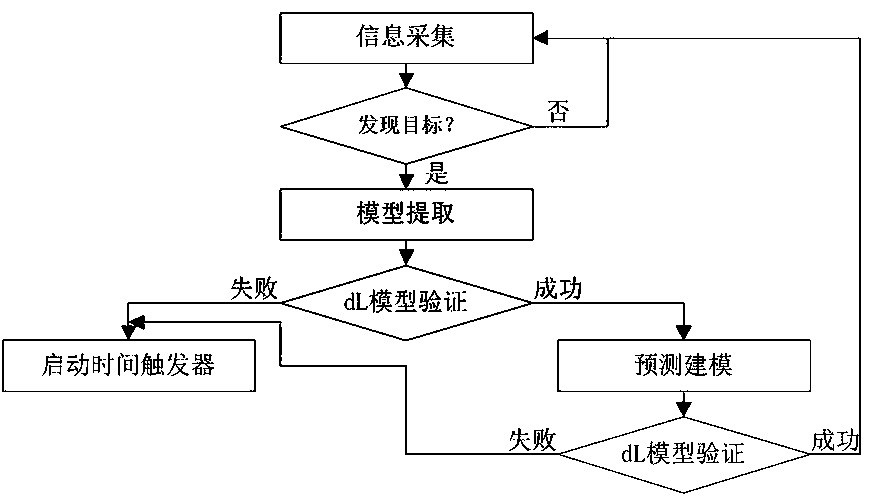
[0049] Attached below Figures 1 to 5 Embodiments of the present invention are described in further detail, as Figure 4 The scene shown: the ship ownship sails freely to the left, τ 0 Sailing horizontally at all times and finding a stationary ship intruder directly ahead, τ 1 always safe but at τ 1 Anticipate collision hazards at all times. Assuming that the information collection period of CPS node equipment is T o 1s, safety prediction time interval Δ τ for 5s and...


PUM


Abstract

The invention is advantageous in that modeling and safety anti-collision decision verification based on dL can be conducted, and the best decision command can be dynamically obtained; the safety of acertain time or a continuous or non-continuous time period of the system can be predicted; the method is good in prediction and flexibility and system simplification.

Description

technical field [0001] The invention belongs to the field of intelligent navigation automatic control of CPS technology, and mainly relates to a CPS anti-collision control method based on differential dynamic logic. Background technique [0002] At present, the anti-collision technology adopted by most or even all means of transportation cannot be more intelligent for safety prediction and flexible navigation of possible collision accidents. In addition, various factors such as weather or human factors lead to frequent collision accidents. Our life safety has been threatened, and also caused great economic losses, so a more intelligent CPS anti-collision control method based on differential dynamic logic (dL) is very important. For example, the anti-collision equipment such as radar or Beidou navigation used by some ships is not effective and cannot be automatically controlled. At the same time, because of the long delay time of the system and the relatively large mass and i...

Claims


Application Information

Patent Timeline
Patent Type & Authority Patents(China)
IPC IPC(8): G05B13/04
Inventor 邱建鹏段鹏飞周颖
Owner SOUTHEAST UNIV
Why Eureka
Try Eureka