
Dustproof and dampproof heat dissipation case

A chassis and dust-proof net technology, applied in instruments, electrical digital data processing, digital data processing components, etc., can solve problems such as inconvenience, electrical components are damp, computers do not take dust-proof measures, etc., to achieve smooth and efficient heat dissipation channels , the effect of simple structure

Inactive Publication Date: 2018-01-09
JINGXI XIUMEI BIANCHENG AGRI SCI & TECH CO LTD
View PDF5 Cites 6 Cited by
  • Summary
  • Abstract
  • Description
  • Claims
  • Application Information

AI Technical Summary

Problems solved by technology

Moisture proof is also a big challenge for computers, especially in the south in spring when the air humidity is high, and the hot and humid air generated by normal computer use will not affect the computer, but if it is not used for a period of time, the humid air will enter The computer case makes the electrical components in the computer damp, which will affect the service life of the computer at least, and short-circuit failure of the computer circuit board at worst
[0003] There are the following problems in the prior art: 1. Most of the computers do not take dust-proof measures, and the dust in the computer needs to be cleaned regularly; Clean the dust-proof net, or if the dust accumulates on the dust-proof net and blocks the air intake channel after a long time, it will affect the heat dissipation function of the chassis and cause more serious consequences. The cleaning steps of the dust-proof net are cumbersome and very inconvenient
3. The case has no moisture-proof and moisture-proof design, especially in the southern spring when returning to the south, humid air entering the case may easily lead to short circuit failure of the host circuit board
4. The heat dissipation channel design of the chassis is unreasonable, and the chassis is often placed in a narrow space, so the hot air discharged from the chassis cannot be dissipated in time and is sucked into the chassis

Method used


Image

  • Dustproof and dampproof heat dissipation case

Examples


Embodiment Construction

[0022] The following will clearly and completely describe the technical solutions in the embodiments of the present invention with reference to the accompanying drawings in the embodiments of the present invention. Obviously, the described embodiments are only some, not all, embodiments of the present invention. Based on the embodiments of the present invention, all other embodiments obtained by persons of ordinary skill in the art without making creative efforts belong to the protection scope of the present invention.

[0023] It should be noted that when a component is said to be "fixed" to another component, it can be directly on the other component or there can also be an intervening component. When a component is said to be "connected" to another component, it may be directly connected to the other component or there may be intervening components at the same time. When a component is said to be "set on" another component, it may be set directly on the other component or t...


PUM


Abstract

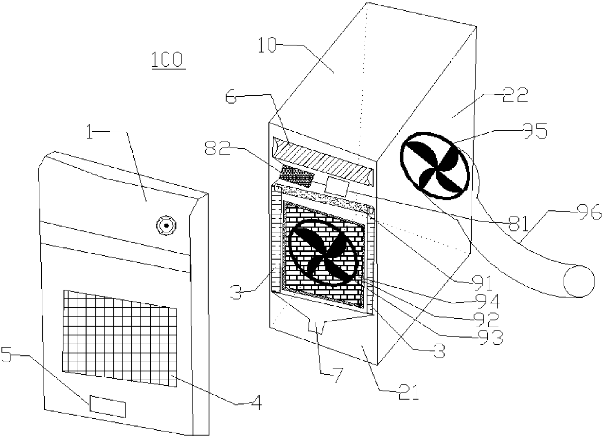
The invention provides a dustproof and dampproof heat dissipation case. The case comprises a shell, a dustproof net, a supply fan and an exhaust fan, wherein multiple air holes are formed at intervalsin the shell to form a grid, the dustproof net covers the air holes, the supply fan is mounted in the shell and faces the air holes, and the exhaust fan is mounted in the shell. The dustproof and dampproof heat dissipation case also comprises a dust brush and a dampproof regulating part, wherein the dust brush is movably mounted in the shell to remove dust on the dustproof net and the grid, and the dampproof regulating part is movably mounted in the shell to close or open the air holes. Through the computer case, dust can be effectively prevented from entering the case, it is not needed to clean the dustproof net frequently, electronic elements in a computer can be effectively protected against damp when the computer is not in use, and heat dissipation performance is good because a heat dissipation system is arranged in the computer case.

Description

【Technical field】 [0001] The invention relates to a computer case, in particular to a dust-proof, moisture-proof and heat-dissipating case. 【Background technique】 [0002] The computer is an indispensable communication and office tool for today's equipment. The computer is mainly composed of a host and a display. During the operation of the computer, the CPU, hard disk, graphics card, power supply and other parts will generate a lot of heat. If the heat is not dissipated in time, Then it will affect the normal operation of the computer. At present, most computers use fans to dissipate heat from the computer. While the fans dissipate heat outward, they also bring a large amount of dust in the air into the computer case. Many computers have the phenomenon of dust accumulation. If the dust is not often If it is cleaned up, it is easy to cause the aging and damage of a large number of hardware inside the computer case. At present, the air inlet of some cabinets adopts the meth...

Claims


Application Information

Patent Timeline
Patent Type & Authority Applications(China)
IPC IPC(8): G06F1/18G06F1/20
Inventor 韩再满
Owner JINGXI XIUMEI BIANCHENG AGRI SCI & TECH CO LTD
Learn More