Bearing structure load transferring framework visualizing method

A load-bearing structure and skeleton technology, applied in special data processing applications, instruments, electrical digital data processing, etc., can solve problems such as inconsistent force transmission skeletons, unreasonable force transmission skeletons, and increased difficulty in solving force transmission skeletons, and achieve operability Strong performance, avoiding the effect of unreasonable force transmission route

Inactive Publication Date: 2018-01-09
YANSHAN UNIV
View PDF2 Cites 6 Cited by
  • Summary
  • Abstract
  • Description
  • Claims
  • Application Information

AI Technical Summary

Problems solved by technology

At present, for the visualization method of the force transmission skeleton of a solid structure, the finite element analysis method integrated in the simulation software is generally used to fit the force transmission skeleton through the obtained stress cloud diagram, but the stress concentration of complex features often leads to the obtained force transmission The skeleton is unreasonable; in addition, topology optimization technology has been developed rapidly in the past two decades, and its main advantage is to redistribute the space of materials when the topological relationship of the structure is unknown, but because the boundary shape of the structure will change during the optimization process , design variables are difficult to quantitatively describe, and the design area is unknown in advance, which greatly increases the difficulty of solving the force transmission skeleton, and the force transmission skeleton obtained under different optimization mathematical models for the same structure is inconsistent, which limits the visualization of the force transmission skeleton to a certain extent the accuracy of

Method used


Image

  • Bearing structure load transferring framework visualizing method
  • Bearing structure load transferring framework visualizing method
  • Bearing structure load transferring framework visualizing method

Examples


Embodiment

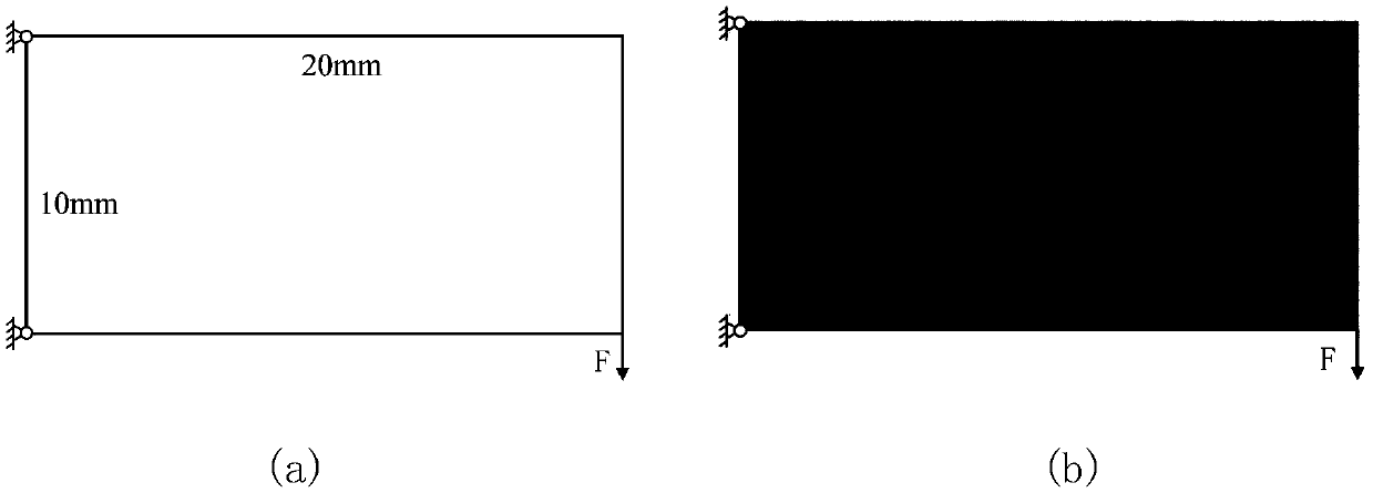
[0036] Taking the rectangular plate whose left end is fixed and the lower boundary point of the right end is loaded by concentrated force as an example, as shown in image 3 Shown in (a), introduce the specific implementation steps of this method.

[0037] (1) Establish the finite element model of the structure. First draw the three-dimensional structure of the rectangular plate in the software Solidworks, such as image 3 In (a), the size of the rectangular plate is set to 20mm*10mm*2mm; then in ANSYS APDL, the finite element type is selected as plane182 element, and the element size is 1mm; the material properties of each element are set, and the elastic modulus is set to 210Gpa, poise The loose ratio was set to 0.3. Constrain all degrees of freedom of the upper and lower boundary nodes at the left end of the model, and apply a vertical downward concentrated force of 50N to the lower boundary node at the right end (node ​​number 2), as shown in image 3 As shown in (b) in...


PUM


Abstract

The invention discloses a bearing structure load transferring framework visualizing method. The bearing structure load transferring framework visualizing method comprising solving the strain energy value of a bearing structure on the basis of finite element theories; sequentially fixing every node, and solving the strain energy value of the bearing structure after boundary conditions change; according to the difference of the strain energy values before and after the boundary conditions change, structuring the stiffness relation between every node and a load point to acquire the strain energycoefficient of every random node which can reflect the stiffness relation between the load point and a random node; according to a strain energy coefficient cloud chart, fitting a load transferring route, namely, a load transferring framework of the bearing structure. The bearing structure load transferring framework visualizing method is based on the finite element theories and fits the load transferring route according to theoretical derivation and numerical analysis, thereby being capable of accurately and conveniently achieving visualization of the load transferring framework of the bearing structure and providing reference for improvement and optimization of solid structures.

Description

technical field [0001] The invention belongs to the field of engineering structure optimization design, and relates to a method for visualizing a force transmission skeleton of a bearing structure. Background technique [0002] In the fields of aerospace, automobiles, ships, etc., the requirements for lightweight equipment and high load-bearing capacity are becoming more and more significant, and the requirements for "global high rigidity" of parts in actual work are also getting higher and higher. Skeleton has become a research hotspot at home and abroad. At present, for the visualization method of the force transmission skeleton of a solid structure, the finite element analysis method integrated in the simulation software is generally used to fit the force transmission skeleton through the obtained stress cloud diagram, but the stress concentration of complex features often leads to the obtained force transmission The skeleton is unreasonable; in addition, topology optimi...

Claims


Application Information

Patent Timeline
Patent Type & Authority Applications(China)
IPC IPC(8): G06F17/50
Inventor 吴凤和王朝华李永欣裴国斌
Owner YANSHAN UNIV
Why Eureka
Try Eureka