
Antenna receiving device

A receiving device and antenna technology, applied in the direction of antenna support/installation device, etc., can solve the problem of low gain and achieve high gain and convenient angle adjustment

Inactive Publication Date: 2018-01-09
天津朝芳科技有限公司
View PDF0 Cites 0 Cited by
  • Summary
  • Abstract
  • Description
  • Claims
  • Application Information

AI Technical Summary

Problems solved by technology

The current receiving antennas used for household equipment such as TV\FM have low gain and cannot meet people's needs. Therefore, it is of great significance to develop an antenna with high gain.

Method used


Image

  • Antenna receiving device

Examples


Embodiment Construction

[0010] Below, the substantive features and advantages of the present invention will be further described in conjunction with examples, but the present invention is not limited to the listed examples.

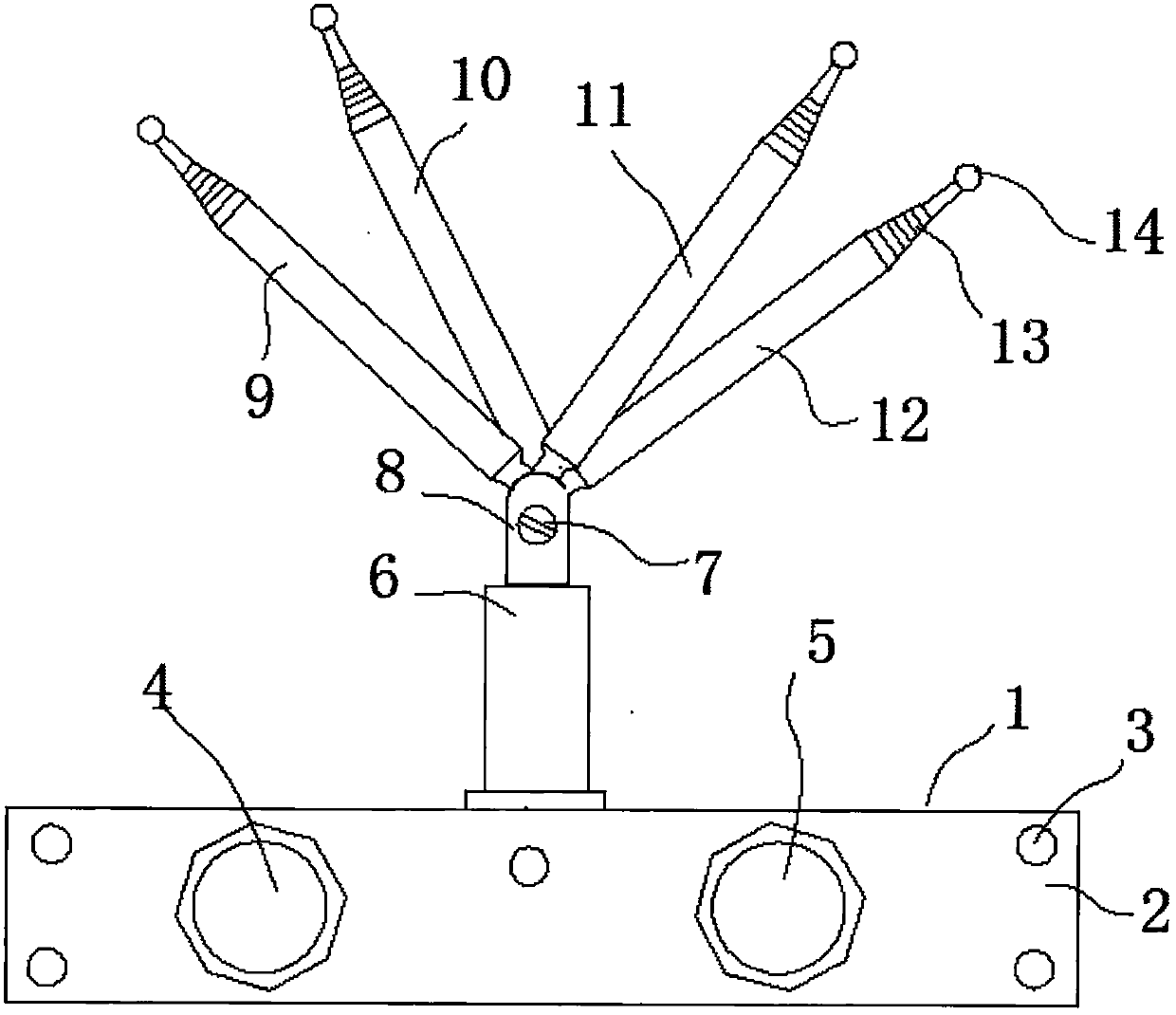
[0011] see figure 1 As shown, an antenna receiving device includes a rectangular housing 1, and the four telescopic antennas on the housing, specifically, the first telescopic antenna 9, the second telescopic antenna 10, the third telescopic antenna 11, The fourth rod antenna 12, the four rod antennas are respectively installed on the housing through four rod antenna bases, the angles of the four rod antennas can be adjusted, and one side of the housing is installed with screws 3 End plate 2, one side of the housing is provided with two terminal posts, the first terminal post 4 and the second terminal post 5; the four rod antenna seats are arranged in a straight line, including the seat body 6 and the The antenna connecting body 8 connected to the seat body, the antenna connect...


PUM


Abstract

The present invention relates to an antenna receiving device, comprising a rectangular housing, on which four rod antennas are mounted, and the four rod antennas are respectively installed on the housing through four rod antenna seats, The angles of the four rod antennas can be adjusted, one side of the housing is provided with an end plate through screws, and two terminals are arranged on one side of the housing; the four rod antennas are seated on a straight line The arrangement includes a seat body and an antenna connection body connected to the seat body, the antenna connection body has a U-shaped portion, the connection end of the telescopic antenna has a bolt hole, and the connection end of the telescopic antenna is inserted into the antenna connection The U-shaped part of the body is locked by bolts. The invention makes the gain of the antenna high, the angle adjustment is convenient, and the antenna is suitable for TV or FM use.

Description

technical field [0001] The invention belongs to the technical field of antennas, and in particular relates to an antenna receiving device. Background technique [0002] As a converter, the antenna converts the guided wave propagating on the transmission line into the electromagnetic wave propagating in the unbounded medium or vice versa. A component used in radio equipment to transmit or receive electromagnetic waves. Engineering systems such as radio communication, broadcasting, television, radar, navigation, electronic countermeasures, remote sensing, and radio astronomy, which use electromagnetic waves to transmit information, rely on antennas to work. In addition, in terms of transmitting energy with electromagnetic waves, non-signal energy radiation also requires antennas. Generally, antennas are reversible, that is, the same antenna can be used as both a transmitting antenna and a receiving antenna. The basic characteristic parameters of the same antenna as transmit...

Claims


Application Information

Patent Timeline
Patent Type & Authority Applications(China)
IPC IPC(8): H01Q1/12
Inventor 刘朝芝
Owner 天津朝芳科技有限公司
Learn More