Permanent magnet motor rotor with high saliency ratio and motor

A permanent magnet motor, salient-to-pole ratio technology, applied in the direction of salient poles, magnetic circuit rotating parts, magnetic circuit shape/style/structure, etc. Problems such as difficult processing and manufacturing, to achieve the effect of improving the salient-to-pole ratio and simple processing

Inactive Publication Date: 2018-01-09
XEMC LIGHT ELECTRIC
View PDF5 Cites 1 Cited by
  • Summary
  • Abstract
  • Description
  • Claims
  • Application Information

AI Technical Summary

Problems solved by technology

[0002] Permanent magnet motors for electric vehicles require a wide range of speed regulation and strong overload capacity. To have such characteristics, it is very important that the salient pole ratio of the motor is required to be large, and the rotor structure of the permanent magnet motor, that is, the shape of the permanent magnet , arrangement, etc., have a great influence on this parameter. The permanent magnets of the traditional permanent magnet motor are arranged in a "one" shape, that is, there are "one"s that match the number of poles in the circumferential direction of the rotor sheet to place the permanent magnets. ""-shaped groove, and there is a magnetic isolation groove between adjacent "one" shapes, but the salient poles of the "one"-shaped arrangement are relatively low. For motors with a large salient pole ratio, the permanent magnets generally adopt a "W"-shaped arrangement. Cloth, that is, in the circumferential direction of the rotor punching sheet, there are evenly arranged "W"-shaped slots matching the number of poles for placing permanent magnets, and magnetic isolation slots are provided between adjacent "W"-shaped slots. The processing and manufacturing of "W" groove is more difficult

Method used


Image

  • Permanent magnet motor rotor with high saliency ratio and motor
  • Permanent magnet motor rotor with high saliency ratio and motor

Examples


Embodiment Construction

[0012] The present invention will be further described in detail below in conjunction with the accompanying drawings and specific embodiments.

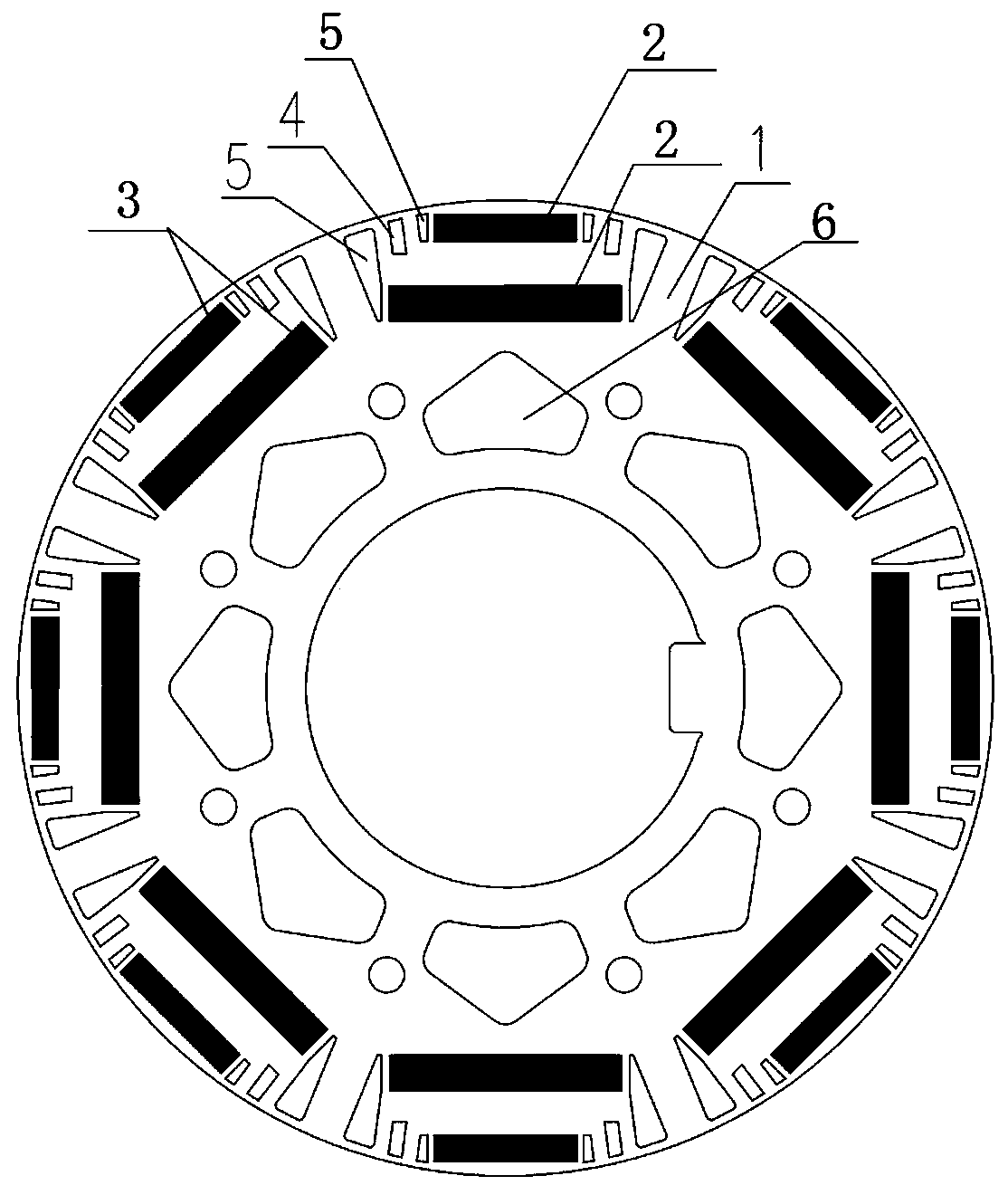
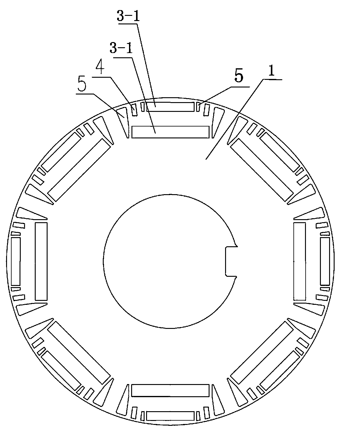
[0013] Referring to the accompanying drawings, a high salient pole ratio permanent magnet motor rotor structure, which includes a rotor punch 1 and a permanent magnet 2, the rotor punch 1 is uniformly provided with a diameter matching the number of poles for placing the permanent magnet 2 in the circumferential direction. To the slot group 3, the radial slot group 3 is provided with two layers of permanent magnet slots 3-1 in the radial direction on the rotor punch 1, and the permanent magnet slots 3-1 are "one" along the circumferential direction of the rotor punch Shaped or "W"-shaped arrangement, the permanent magnets 2 are placed in the permanent magnet slots 3-1, and magnetic isolation slots 5 are provided at both ends of each permanent magnet slot 3-1, in order to further improve the salient pole It also includes performance opt...


PUM


Abstract

The present invention relates to a permanent magnet motor rotor with a high saliency ratio. The permanent magnet motor rotor with a high saliency ratio comprises a rotor sheet and permanent magnets; radial slot sets configured to put the permanent magnets and matching with the number of poles are uniformly arranged at a circumference direction of the rotor sheet, the radial slot sets are two or more than two layers of permanent magnet slots arranged on the rotor sheet along a radial direction, the permanent magnet slots are distributed in a line-shaped mode or a W-shaped mode along the circumference of the rotor sheet, the permanent magnets are arranged in the permanent magnet slots, and two ends of each permanent magnet slot are respectively provided with non-magnetic slots. The radial slot sets configured to put the permanent magnets and matching with the number of poles are uniformly arranged at the circumference direction of the rotor sheet, and a plurality of permanent magnets arearranged at each pole, so that a saliency ratio is greatly improved, and processing is very simple. The present invention further relates to a motor comprising the permanent magnet motor rotor with ahigh saliency ratio.

Description

technical field [0001] The invention relates to the field of motors, in particular to a high salient pole ratio permanent magnet motor rotor and motor. Background technique [0002] Permanent magnet motors for electric vehicles require a wide range of speed regulation and strong overload capacity. To have such characteristics, it is very important that the salient pole ratio of the motor is required to be large, and the rotor structure of the permanent magnet motor, that is, the shape of the permanent magnet , arrangement, etc., have a great influence on this parameter. The permanent magnets of the traditional permanent magnet motor are arranged in a "one" shape, that is, there are "one"s that match the number of poles in the circumferential direction of the rotor sheet to place the permanent magnets. ""-shaped groove, and there is a magnetic isolation groove between adjacent "one" shapes, but the salient poles of the "one"-shaped arrangement are relatively low. For motors w...

Claims


Application Information

Patent Timeline
Patent Type & Authority Applications(China)
IPC IPC(8): H02K1/08H02K1/27
Inventor 毛勇徐卫东谭咸伟刘小军胡智光
Owner XEMC LIGHT ELECTRIC
Why Eureka
Try Eureka