Novel high-speed rail shaft monitoring system

A monitoring device, high-speed rail technology, applied in electrical components, piezoelectric effect/electrostrictive or magnetostrictive motors, generators/motors, etc., can solve the problems of low reliability and narrow effective bandwidth, and achieve reliability The effect of high, effective frequency bandwidth, strong power generation and power supply capacity

Active Publication Date: 2018-01-09
ZHEJIANG NORMAL UNIVERSITY
View PDF4 Cites 4 Cited by
  • Summary
  • Abstract
  • Description
  • Claims
  • Application Information

AI Technical Summary

Problems solved by technology

In order to solve the power supply problem of the train shafting real-time monitoring system, scholars at home and abroad have proposed a micro-sized piezoelectric generator that can be integrated with the monitoring system, but the existing piezoelectric generator is periodically excited and the piezoelectric sheet is subjected to alternating tension. Compressive stress, so the reliability is low and the effective bandwidth is narrow

Method used


Image

  • Novel high-speed rail shaft monitoring system
  • Novel high-speed rail shaft monitoring system
  • Novel high-speed rail shaft monitoring system

Examples


Embodiment Construction

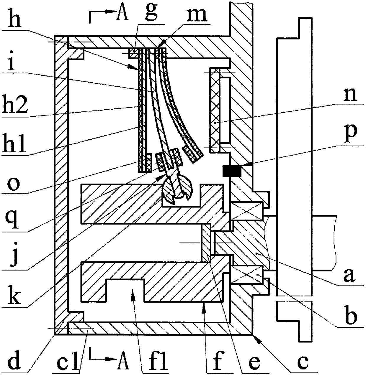
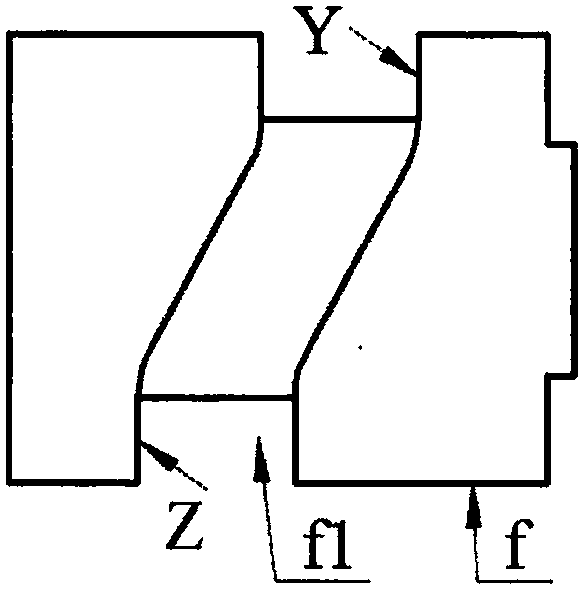
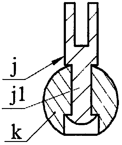
[0013] The axle a is installed on the frame c through the bearing b, the end of the shell c1 on the frame c is installed with the end cover d through the screw; the end of the axle a is installed with the cylindrical cam with the cam groove f1 through the pressure plate e and the screw f, one end of the cylindrical cam f is set on the wheel shaft a and leans against the inner ring of the bearing b; the boss of the shell c1 of the frame c is installed with a piezoelectric vibrator h and a reed i through a pressure block g and screws , the free end of the reed i is embedded in the groove of the exciter j; the left and right ends of the exciter j are equipped with a suspension magnet q, and the suspension magnet q, the exciter j and the reed i are fixedly connected by bolts; There is a guide post j1, and a rolling body k is set on the guide post j1, the rolling body k is cylindrical or spherical, and the rolling body k is placed in the cam groove f1; the piezoelectric vibrator h i...


PUM


Abstract

The invention relates to a novel high-speed rail shaft monitoring system, and belongs to the field of rail vehicle monitoring and piezoelectric power generation. A wheel shaft is arranged on a frame via a bearing, an end cover is arranged at an end part of a shell of the frame, a cylindrical cam with a cam groove is arranged at an end part of the wheel shaft, one end of the cylindrical cam sleevesthe wheel shaft and props against to an inner ring of the bearing, piezoelectric vibrators and a spring sheet are arranged on a boss of the shell of the frame, a free end of the spring sheet is embedded into a groove of an exciter, a guide post is arranged on the exciter, a rolling body sleeves the guide post and is in a cylindrical or spherical shape, the rolling body is arranged in the cam groove, each piezoelectric vibrator is formed by splicing a substrate and a piezoelectric sheet, the piezoelectric vibrators are symmetrically arranged at two sides of the spring sheet, the substrate is arranged near to the spring sheet, a gasket is crimped between the substrate and the spring sheet, suspended magnets are arranged at free ends of the piezoelectric vibrators, a circuit board and a sensor are arranged on the frame, the piezoelectric vibrators are connected with the circuit board via wires, and the circuit board is connected with the sensor via a wire.

Description

technical field [0001] The invention belongs to the technical field of rail transit monitoring and piezoelectric power generation, and in particular relates to a novel high-speed rail shaft system monitoring device. Background technique [0002] The normal operation of rail train wheels is the key to ensure the safe operation of rail vehicles. In the past, the health status of the key components of rail vehicle wheel trains was guaranteed by regular maintenance and overhaul; with the continuous improvement of vehicle operating speed and the improvement of people's safety awareness, the research on real-time online monitoring technology of wheel sets during vehicle operation has been favored by domestic and foreign countries. Widely concerned by foreign scholars, the required monitoring elements include shaft and bearing temperature, rotational speed, dynamic stiffness, wear and vibration, and many other aspects. For the wheel set monitoring system, the ideal method is to in...

Claims


Application Information

Patent Timeline
IPC IPC(8): H02N2/18
Inventor 马继杰曹渊何恒钱
Owner ZHEJIANG NORMAL UNIVERSITY
Why Eureka
Try Eureka