Space network on-demand access system

A space network and access system technology, applied in the transmission system, radio transmission system, electrical components, etc., can solve the problems of unfavorable user experience, multi-user scheduling, short signal access time, long signal access time, etc., to achieve convenient Expansion of channels and processing capabilities, short signal access time, solving the effect of slow capture speed

Active Publication Date: 2020-04-28
10TH RES INST OF CETC
View PDF12 Cites 0 Cited by
  • Summary
  • Abstract
  • Description
  • Claims
  • Application Information

AI Technical Summary

Problems solved by technology

[0011] 1. For low-orbit aircraft, the speed near the ground often reaches several kilometers to more than ten kilometers per second. The relatively large moving speed leads to a very large Doppler introduced. The result is: 1. When the computing resources are small, The signal access time is very long, which is not conducive to user experience and multi-user scheduling, and the interruption time is also very long during synchronous satellite handover; 2. In order to make the signal access time short, a large number of computing resources are required for parallel operation. It is not conducive to the unitization and chipping of the receiver, which further increases the cost
[0012] 2. The data path composed of optical fiber switching matrix or single-pole multi-throw switch is based on physical devices, which is not only expensive, but also occupies a large volume. In the environment of increasing processing capacity, channel expansion is difficult
Under such conditions, the disadvantages of digital chips in terms of reconfiguration are highlighted, and they do not have the characteristics of software defining everything.

Method used


Image

  • Space network on-demand access system
  • Space network on-demand access system
  • Space network on-demand access system

Examples


Embodiment Construction

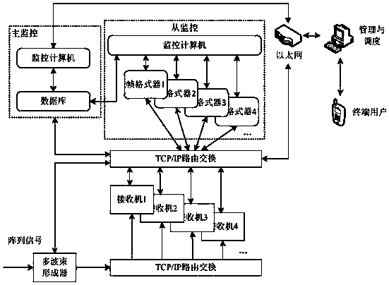
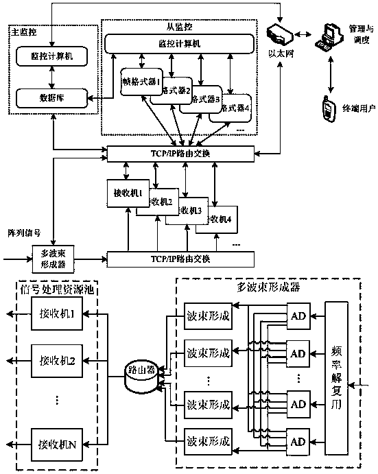
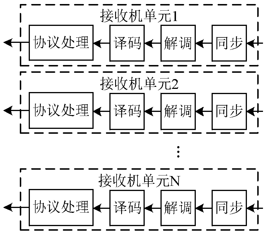
[0027] refer to figure 1. In the embodiment described below, a kind of space network on-demand access system has a main monitoring computer and a slave monitoring computer comprising a monitoring computer, a TCP / In the IP routing switching unit, the multi-beamformer is aimed at the end user aircraft, and according to the azimuth information issued by the main monitoring computer, the beamforming is performed on the input array signal, and the Doppler prior information is obtained through the satellite orbit information, and the output The digital signal after the spatial filtering of the Doppler information forms a TCP / IP data packet and transmits it to the TCP / IP routing switching unit; the TCP / IP routing switching unit forwards the TCP / IP data packet to the specified IP address according to the IP address specified by the main monitoring computer. Receiver unit; the receiver unit deframes, synchronizes, demodulates and decodes the UDP data packet combined with the Doppler...


PUM


Abstract

The invention provides spatial network on-demand access system architecture. By using the architecture provided by the invention, the defects that a traditional access system is slow in signal capturespeed, poor in hardware expansibility and high in coupling between software can be solved. The spatial network on-demand access system architecture is implemented via the technical scheme as follows:a multi-beam former performs beam forming on an input array signal according to azimuth information issued by a master monitoring computer, Doppler prior information is acquired via satellite orbit information, digital signals formed by the output Doppler information after spatial filtering are enabled to form into a TCP / IP data packet to be transmitted to a TCP / IP route switching unit, and the TCP / IP data packet is forwarded to a specified receiver unit; the receiver unit performs de-framing, synchronization, demodulation and decoding on a UDP data packet in combination with the Doppler information issued by the master monitoring computer, and forwards the decoded data packet to a frame formatter of a slave monitoring computer to extract data in the TCP / IP data packet, and the data is transferred to a system management and scheduling unit after framing to be distributed to a terminal user putting forward a task application.

Description

technical field [0001] The invention relates to a space high-speed backbone network constructed with tracking and data relay satellites and broadband communication satellites as the core, and a space information access network composed of special satellite systems such as remote sensing information acquisition and meteorological environment monitoring. It relates to the field of satellite communication and utilizes Geostationary orbit satellites are used as transponders to enable aircraft at any location to communicate with end users at fixed locations on the ground. [0002] technical background [0003] At present, location service applications based on wireless communication network and mobile positioning technology are more and more concerned and valued by the industry and become the hot spot of current information competition. There are many types of spatial location services, and information services based on spatial location provided by a single technology cannot reall...

Claims


Application Information

Patent Timeline
Patent Type & Authority Patents(China)
IPC IPC(8): H04B7/185H04L29/06
Inventor 汤辉袁田徐会忠
Owner 10TH RES INST OF CETC
Why Eureka
Try Eureka