Eureka AIR delivers breakthrough ideas for toughest innovation challenges, trusted by R&D personnel around the world.

Fault detection system

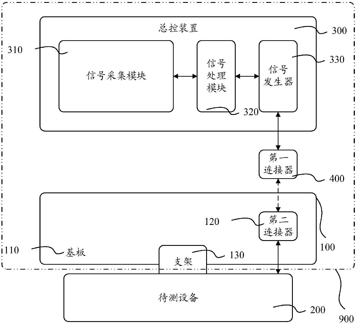
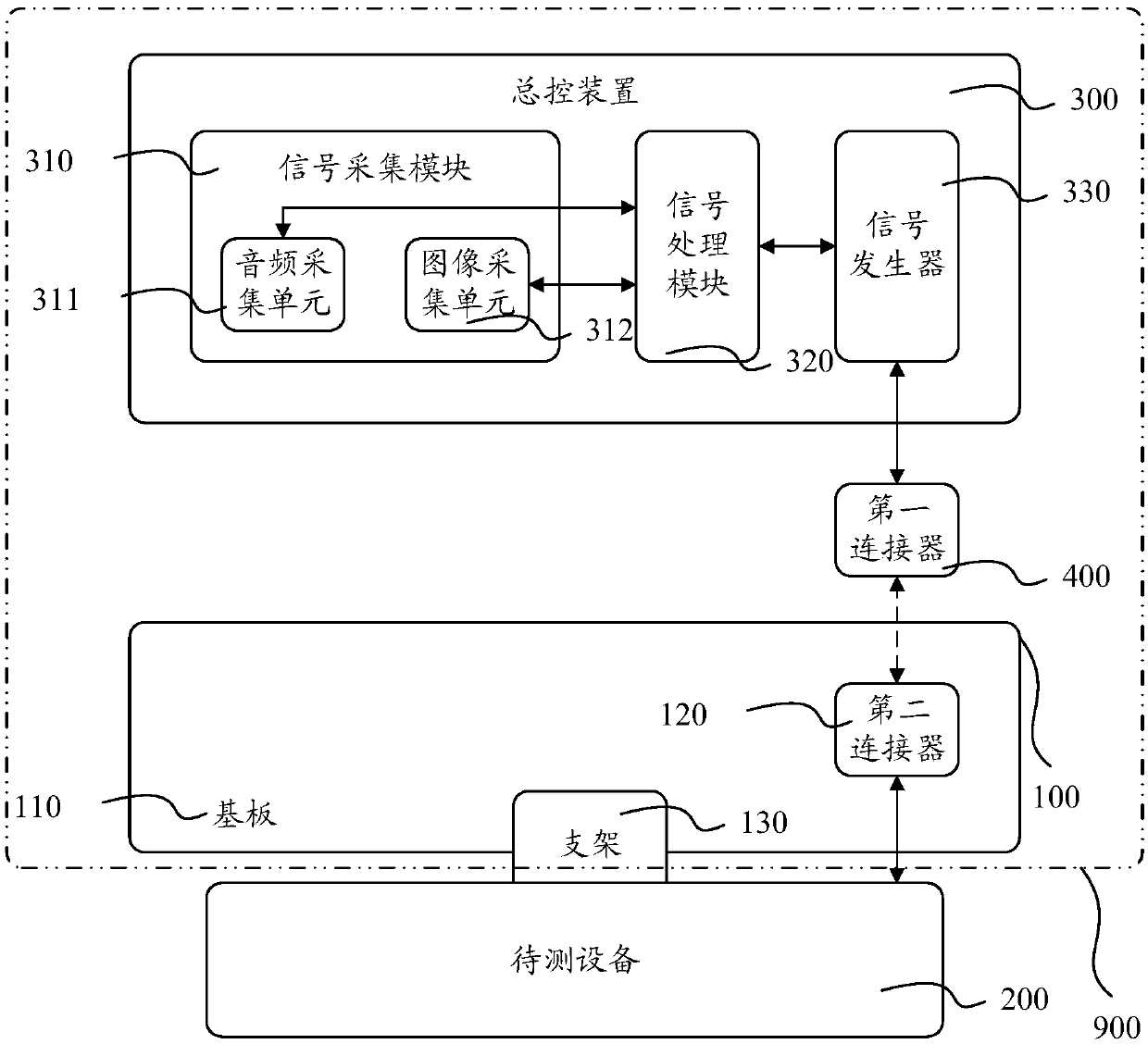
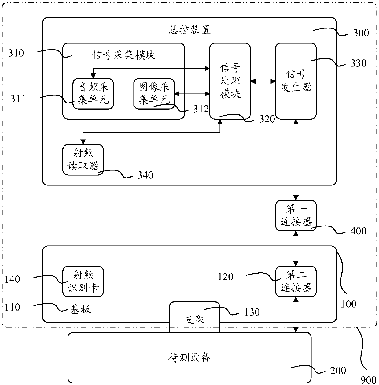
A technology for fault detection and equipment under test, which is applied in television, electrical components, image communication, etc., can solve problems affecting test efficiency and achieve the effect of improving efficiency, accuracy and stability

Inactive Publication Date: 2018-01-09
GUANGZHOU SHIYUAN ELECTRONICS CO LTD +1
View PDF7 Cites 2 Cited by
  • Summary
  • Abstract
  • Description
  • Claims
  • Application Information

AI Technical Summary

Problems solved by technology

[0003] The invention provides a fault detection system to overcome the problem that when the traditional tooling board is used to test the equipment to be tested, the workers at each detection station need to connect and disconnect the wires, which affects the test efficiency

Method used


Image

  • Fault detection system
  • Fault detection system
  • Fault detection system

Examples


Embodiment Construction

[0035] Reference will now be made in detail to the exemplary embodiments, examples of which are illustrated in the accompanying drawings. When the following description refers to the accompanying drawings, the same numerals in different drawings refer to the same or similar elements unless otherwise indicated. The implementations described in the following exemplary examples do not represent all implementations consistent with the present invention. Rather, they are merely examples of apparatuses and methods consistent with aspects of the invention as recited in the appended claims.

[0036] The terminology used in the present invention is for the purpose of describing particular embodiments only and is not intended to limit the invention. As used herein and in the appended claims, the singular forms "a", "the", and "the" are intended to include the plural forms as well, unless the context clearly dictates otherwise. It should also be understood that the term "and / or" as use...


PUM


Abstract

The invention provides a fault detection system. The fault detection system comprises a tooling plate, a general control device and a first connector; the second connector in the tooling plate is connected with equipment to be detected; the signal generator in the general control device is connected with the first connector; when a test needs to be carried out, the first connector is controlled tobe in abutting joint with the second connector; and a signal processing module can notify a signal generation unit to send an audio and video signal to the equipment to be detected to test. By meansof the fault detection system provided by the invention, each worker does not need to connect and separate a line; furthermore, line connection can be carried out before the equipment to be detected enters production line flow; the production line operation is not influenced by the line connection process; artificial participation is unnecessary in the test process; therefore, the production lineoperation stability is improved; and thus, the detection efficiency and precision are greatly improved.

Description

technical field [0001] The invention relates to the field of equipment testing, in particular to a fault detection system. Background technique [0002] At present, the production and assembly of complete TV sets usually adopts an assembly line operation method. The assembly line is equipped with assembly stations for various components, debugging and testing stations for various items, and repair stations in accordance with the sequence of procedures. The production line drives the tooling board carrying the TV to each station to perform the corresponding process. The operation on the testing station is generally to insert the testing line of the corresponding item on the TV into the interface of the corresponding testing equipment, and then use the manual control method for testing, and the workers need to switch the TV channel through the remote control and observe the TV with naked eyes Whether the display of the VGA channel screen is normal. However, manual detection...

Claims


Application Information

Patent Timeline
IPC IPC(8): H04N17/00H04N17/04
Inventor 辛奇俊
Owner GUANGZHOU SHIYUAN ELECTRONICS CO LTD
Why Eureka
Eureka Blog
Learn More