
Power conversion circuit board, and electric compressor

A technology for power conversion and circuit substrates, applied to circuit devices, machines/engines, printed circuit components, etc., to reduce the impact and achieve high withstand voltage effects

Inactive Publication Date: 2018-01-09
MITSUBISHI HEAVY IND THERMAL SYST
View PDF7 Cites 0 Cited by
  • Summary
  • Abstract
  • Description
  • Claims
  • Application Information

AI Technical Summary

Problems solved by technology

However, in recent years, due to changes in the environment based on new technology development, there is a possibility that an input of 1000V or more is required as a voltage power supply

Method used


Image

  • Power conversion circuit board, and electric compressor
  • Power conversion circuit board, and electric compressor
  • Power conversion circuit board, and electric compressor

Examples


no. 1 approach

[0042] Below, refer to Figure 1 to Figure 7 The circuit board for power conversion according to the first embodiment will be described.

[0043] (the whole frame)

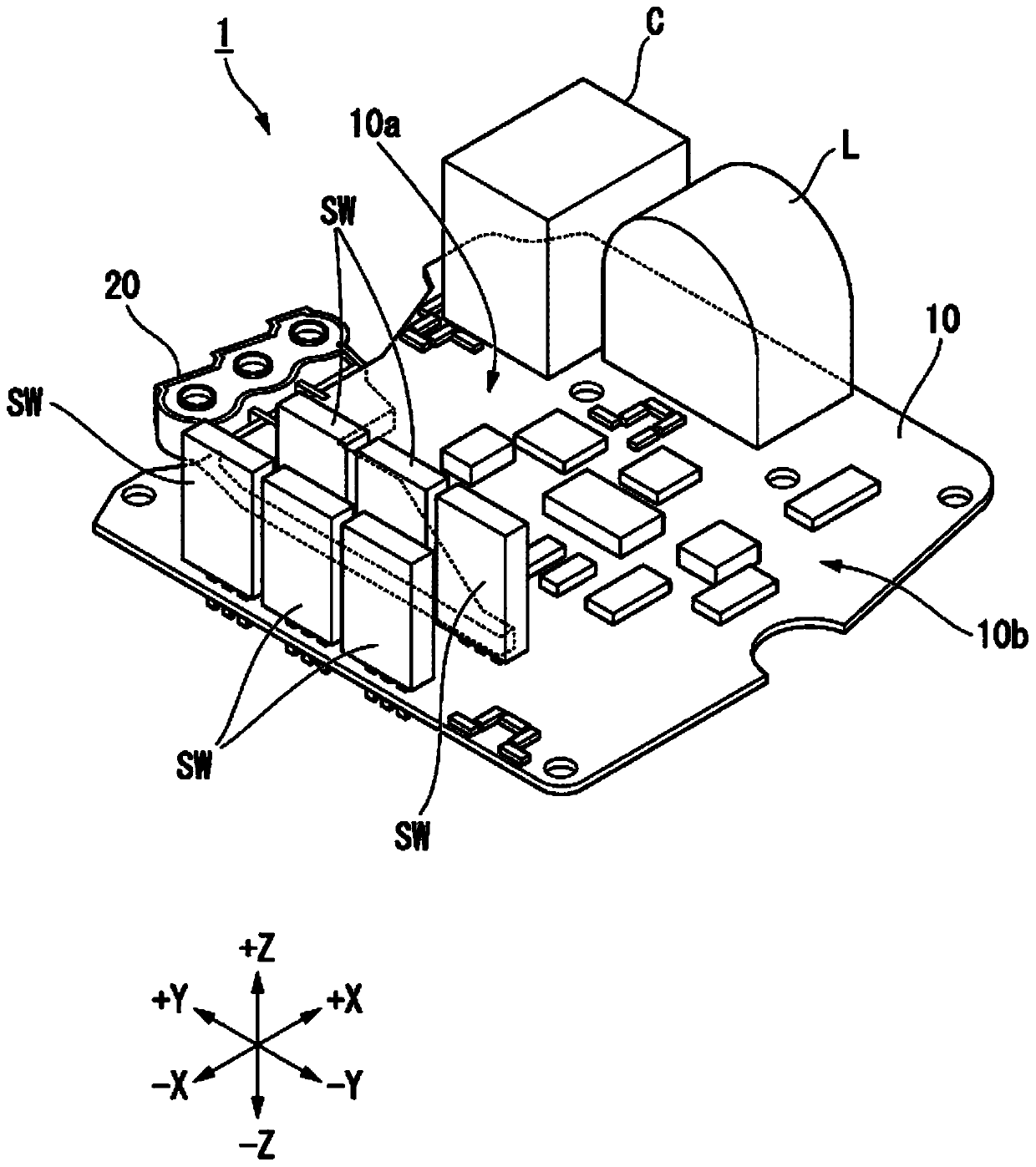
[0044] figure 1 It is a perspective view of the circuit board for electric power conversion concerning 1st Embodiment.

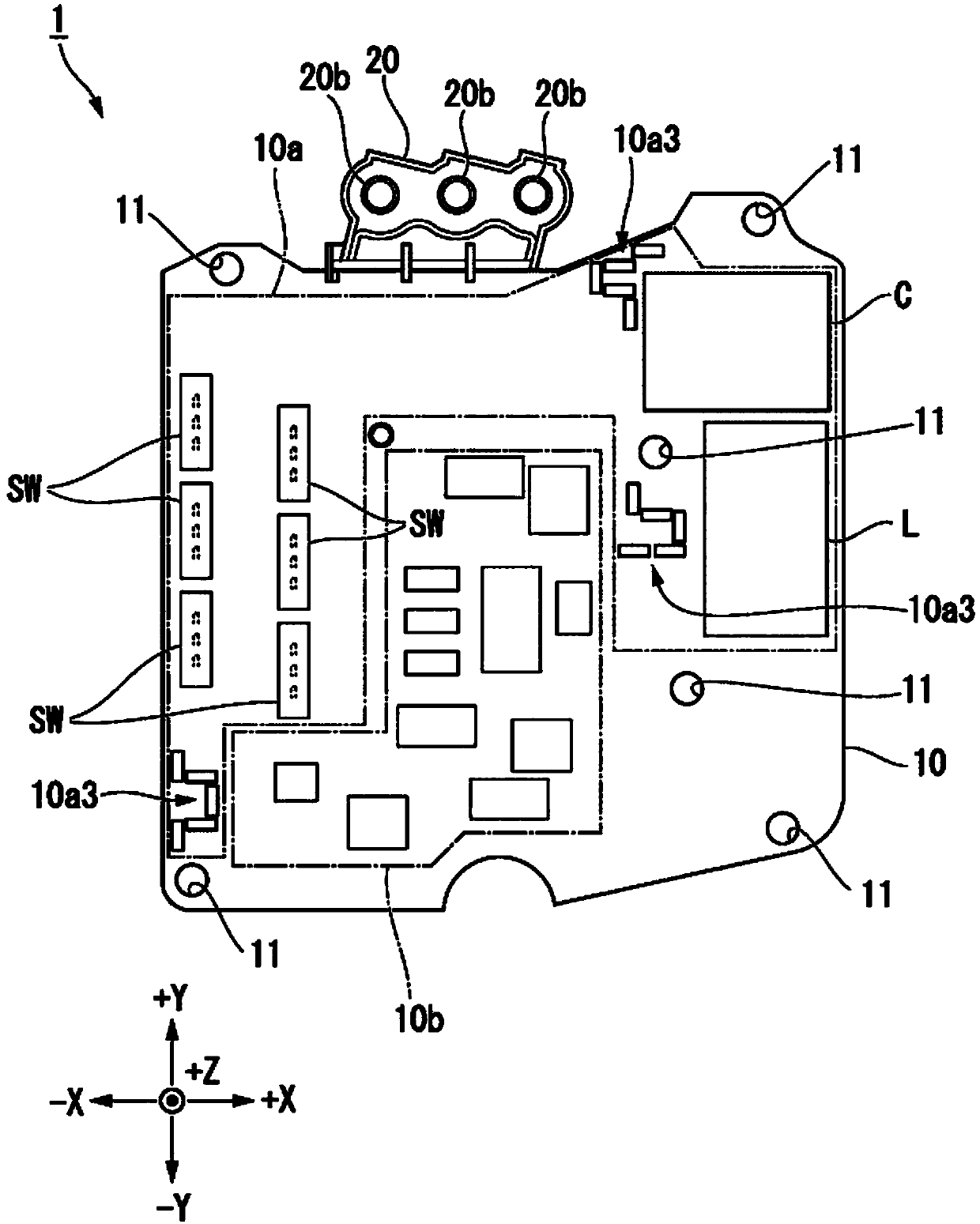
[0045] in addition, figure 2 It is a top view of the circuit board for power conversion concerning 1st Embodiment.

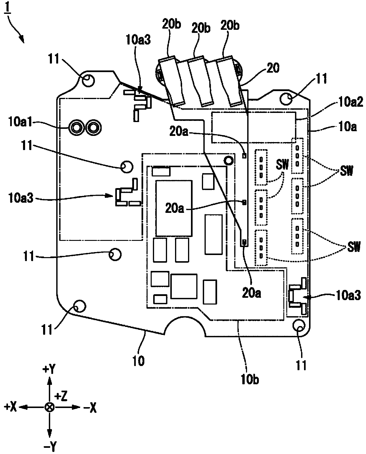
[0046] in addition, image 3 It is a bottom view of the circuit board for power conversion concerning 1st Embodiment.

[0047] in addition, Figure 4 It is a side view of the circuit board for power conversion concerning 1st Embodiment.

[0048] in addition, Figure 5 It is a front view of the circuit board for electric power conversion concerning 1st Embodiment.

[0049] The power conversion circuit board 1 according to the first embodiment is a circuit board constituting an inverter that converts DC power supplied from outside through input terminals (described later) ...


PUM


Abstract

This power conversion circuit board (1) has a power conversion circuit mounted thereon for converting direct current to alternating current, and comprises a low voltage circuit, to which a low voltageis applied, and a high-voltage circuit (10a), to which a high voltage is applied, separated into different areas on the same board surface. Further, the high-voltage circuit (10a) is configured froma busbar, with part of the wiring thereof formed on the board surface, and the other part of said wiring separated by a prescribed distance from the board surface.

Description

technical field [0001] The invention relates to a circuit substrate for power conversion and an electric compressor. [0002] This application claims priority to Patent Application No. 2015-060840 filed in Japan on March 24, 2015, and uses the contents thereof here. Background technique [0003] For example, because it is necessary to accommodate various structural equipment in a limited space in a vehicle, a high space-saving property is required for a vehicle-mounted air conditioner. Therefore, in recent years, for the purpose of improving space saving, an integrated electric compressor (for example, refer to Patent Documents 1 and 2) is provided. A motor for driving the compressor and a circuit board for controlling the compressor are integrally formed. [0004] prior art literature [0005] patent documents [0006] Patent Document 1: Japanese Patent Application Laid-Open No. 2008-099480 [0007] Patent Document 2: Japanese Patent Application Laid-Open No. 2011-2293...

Claims


Application Information

Patent Timeline
IPC IPC(8): H02M7/48F04B39/00
CPCH02M7/003H01G2/06H05K1/0231H02M7/48F04B35/04F04B39/00F04B17/03H02M7/53F04B49/06
Inventor 服部诚上谷洋行樋口博人
Owner MITSUBISHI HEAVY IND THERMAL SYST
Learn More