
Orthopedic operation assist device

An orthopedic surgery and auxiliary device technology, applied in the field of orthopedic surgery, can solve problems such as inconvenience in use, and achieve the effects of convenient use, simple and elegant overall structure, and accurate displacement and movement.

Inactive Publication Date: 2018-01-12
HENAN UNIV OF CHINESE MEDICINE
View PDF10 Cites 4 Cited by
  • Summary
  • Abstract
  • Description
  • Claims
  • Application Information

AI Technical Summary

Problems solved by technology

[0017] In view of the above situation, in order to overcome the defects of the prior art, the present invention provides an orthopedic surgery aid, which effectively solves the problem of inconvenient use of the existing annular external fixation device when docking bones

Method used


Image

  • Orthopedic operation assist device
  • Orthopedic operation assist device
  • Orthopedic operation assist device

Examples


Embodiment 1

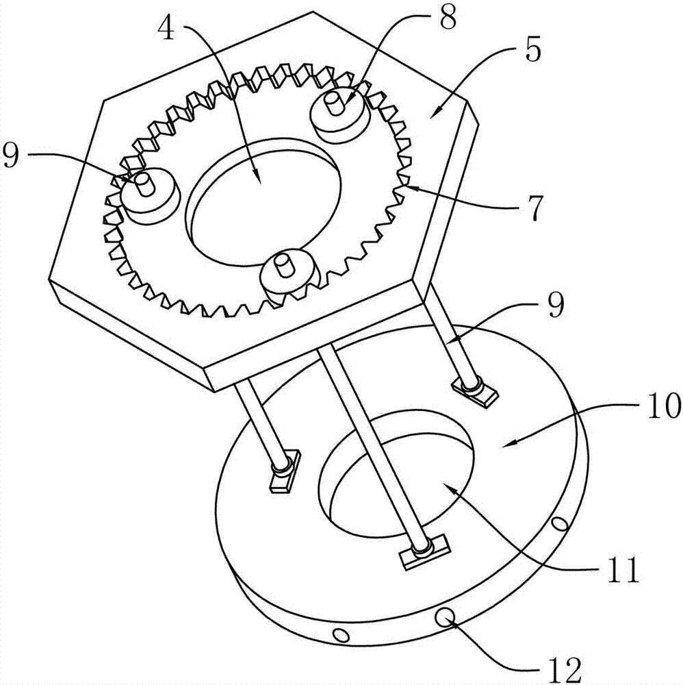
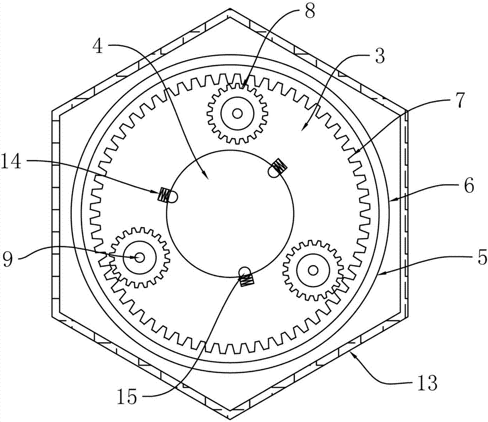
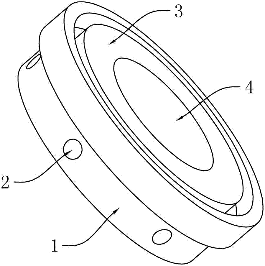
[0037] Embodiment 1, the present invention is an orthopedic surgery aid, which mainly includes an annular fixing seat 1, and a transparent first fixing hole 2 is opened on the side edge of the ring, and the first fixing hole 2 is mainly used to place a Kirschner wire Or puncture a needle or pedicle screw, the top of the annular fixing seat 1 is also connected with a guide rail disc 3, and the central axis position of the guide rail disc 3 and the annular fixing seat 1 is provided with a first through hole 4, and the main body in the first through hole 4 It is used to pass through the patient's legs, arms or bones. On the guide rail disc 3, a gear disc 5 that can rotate in the guide rail disc 3 is installed and fixed. The reason why the gear disc 5 can rotate is that it is integrally connected with a The rotating body 6 that can rotate in the guide rail disc 3 is mainly responsible for realizing the rotation, so the corresponding guide rail disc 3 is provided with a guide rail g...

Embodiment 2

[0042] Embodiment 2. On the basis of Embodiment 1, there are many types of rotating body 6, as long as the gear plate 5 can be fixedly rotated. Preferably, the rotating body 6 can choose a rotating block, but the rotating block can be a friction block. Rotate, when no force is used, the gear disc 5 will not automatically rotate, and when an active force is applied, the gear disc 5 can be rotated.

Embodiment 3

[0043] Embodiment 3. On the basis of Embodiment 1, the rotating body 6 can also be selected as a rotating bead. The rotating bead only ensures ground contact and is convenient to rotate. It can be guaranteed that it is difficult to rotate. It is difficult to rotate, which does not mean that it does not rotate, but that it needs to rely on a certain force to rotate.


PUM


Abstract

The invention relates to an orthopedic operation assist device, and effectively solves the problem of inconvenience in use of an existing annular outer fixing device when bones are abutted. The technical scheme includes that the orthopedic operation assist device comprises an annular fixed seat, a plurality of first fixed holes are horizontally formed in the annular fixed seat, a guide rail disk is integrally connected on the upper portion of the annular fixed seat, a first axial through hole is formed in the guide rail disk and the annular fixed seat, a gear disk is fixedly mounted on the guide rail disk and can rotate in the guide rail disk, a rotating body is integrally connected on the lower portion of the gear disk and can rotate in the guide rail disk, an inner gear is arranged on the gear disk and is meshed with three small gears fixed on the guide rail disk, a threaded rod penetrates a center shaft of each small gear and is connected with the corresponding threaded rod in a threaded and matched manner, the lower ends of the threaded rods are connected with an adjusting disk, second axial through holes are formed in the adjusting disk, and a plurality of second fixing holesare formed in the lower end of the adjusting disk. The orthopedic operation assist device is convenient to use, the bones are accurate to move and convenient to rotate, the usage quantity of Kirschnerwires is small, and the bones of a patient are rapidly healed.

Description

technical field [0001] The invention relates to the technical field of orthopedic surgery, in particular to an orthopedic surgical aid used in surgery. Background technique [0002] Fracture treatment has been paid more attention from ancient times to the present, and has experienced simple external fixation, traction reduction, open coverage and internal and external fixation. In the 1950s, Russia's Llizarov pioneered the technology of circular external fixator. At present, external fixator has become a routine method for fracture treatment at home and abroad. When performing orthopedic surgery, external fixation has the following advantages: [0003] 1. It is easy to operate, it can be closed for needle threading, and it can also be opened and reset for needle threading; [0004] 2. It is firmly fixed, and the tightness and direction can be adjusted at any time; [0005] Maximize the protection of the blood supply at the fracture without peeling off the periosteum, so th...

Claims


Application Information

Patent Timeline
Patent Type & Authority Applications(China)
IPC IPC(8): A61B17/62
Inventor 岳宗进于露刘汝银彭晓艳鲁花冯仲锴王新立王西彬李云朋许大勇
Owner HENAN UNIV OF CHINESE MEDICINE
Learn More