Arc energy control method and control device, computer readable medium

An arc energy and control method technology, applied in the direction of adjusting electric variables, arc welding equipment, control/regulating systems, etc., can solve the problems of poor heat input control effect and inability to control welding power output, etc., to achieve good quality, heat input small amount of effect

Active Publication Date: 2019-03-19
HUAHENG WELDING
View PDF5 Cites 0 Cited by
  • Summary
  • Abstract
  • Description
  • Claims
  • Application Information

AI Technical Summary

Problems solved by technology

[0004] However, for oscillating arc welding, the current control method of arc heat only considers the welding power output control when the arc is at the edge of the weld, and the current value at the edge of the weld can only be selected between the pulse peak value and the base value, For the position where the arc is outside the edge of the weld, it is impossible to control the output of the welding power source, so that when the arc reaches the edge of the weld, the current needs to be increased or decreased instantaneously and the value is quite different from the peak base value of the welding pulse. , it cannot be applied
In addition, for narrow-gap welding, the tungsten electrode makes a pendulum motion around one end, and its effective arc length changes with the swing time, that is, the heat input by the arc to the workpiece changes from time to time. At this time, the existing scheme is only used to control the arc reaching the edge. The output of the welding power source is relatively small, and the control effect on the heat input is poor
Therefore, for oscillating arc welding, there is currently no better solution that can control the heat input in real time to ensure the fatigue strength, low-temperature impact toughness or intergranular corrosion resistance of the product.

Method used


Image

  • Arc energy control method and control device, computer readable medium
  • Arc energy control method and control device, computer readable medium
  • Arc energy control method and control device, computer readable medium

Examples


Embodiment Construction

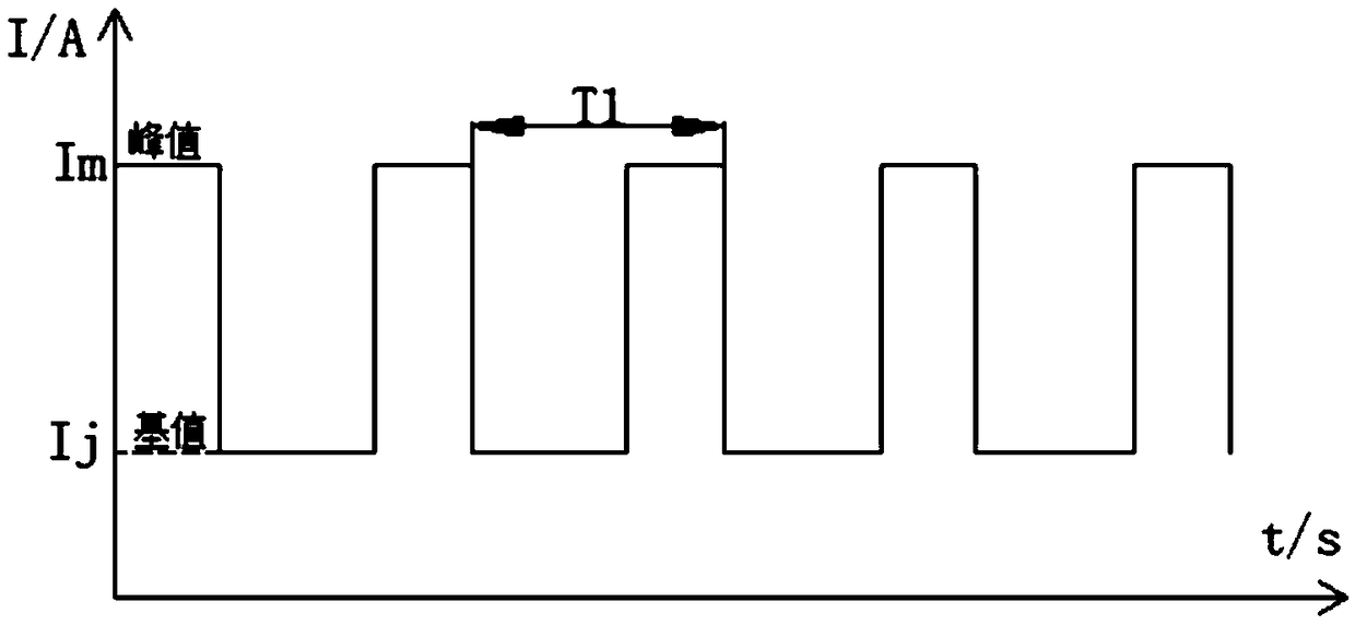
[0037] figure 1 A schematic diagram of the output waveform of an existing pulse welding power supply is given. In the existing pulse welding, the welding power supply periodically outputs pulse current I (unit is ampere A) with time t (unit is second s), the period of pulse current is T1, the peak value of pulse current is Im, and the pulse current The base value of is Ij.

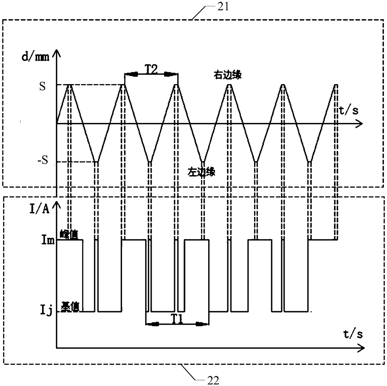
[0038] For oscillating arc welding, the existing control method based on the arc position is applied to control the output current of the pulse welding during the welding process. When the arc reaches the edge of the weld, the output of the welding power supply is forced to the base value of the pulse current or pulse peak current. The schematic diagram of the power output waveform of pulse welding based on arc position control is as follows: figure 2 shown.

[0039] see figure 2 , the upper figure 21 is a schematic diagram of the periodic swing of the arc position with time t (unit is second s), wh...


PUM


Abstract

The invention discloses a control method and device for arc energy and a computer readable medium. The control method for the arc energy includes the steps that a welding joint form is obtained; the arc position and the welding power source output synchronous mode are determined based on the obtained welding joint form; and output currents of a welding power source are controlled in real time based on changes of the determined synchronous mode and the determined arc position. By the adoption of the above scheme, the output currents of the welding power source are controlled in real time basedon the synchronous mode and the arc position, the heat input amount in the arc swing process can be controlled in real time according to the arc position, the expected welding effect can be achieved,in addition, the heat input amount of the arc can be small as much as possible, and therefore a welding connector with better quality is obtained.

Description

technical field [0001] Embodiments of the present invention relate to the field of welding, and in particular, to a control method and control device for arc energy, and a computer readable medium. Background technique [0002] Among various welding methods, arc welding is the most widely used welding method, and arc is the most obvious distinguishing feature of arc welding compared with other welding methods. The arc is an energy carrier, which can convert the electric energy output by the welding power source into light and heat energy and transfer it to the base material of the workpiece. It consists of three parts: the cathode area, the anode area and the arc column area. For different arc welding methods, the area where the arc heat is concentrated is also different. For example, the heat of plasma arc welding is concentrated in the arc column area, and the heat of tungsten argon arc welding is concentrated in the anode area. In the actual welding process, it is necess...

Claims


Application Information

Patent Timeline
Patent Type & Authority Patents(China)
IPC IPC(8): G05F1/02B23K9/095
Inventor 周有泉李延军蒋昱宏
Owner HUAHENG WELDING
Why Eureka
Try Eureka