
Synchronous assembly and disassembly device for rotating and static ring components of stern shaft sealing device

A sealing device and component technology, which is applied to ship components, transportation and packaging, ships, etc., can solve problems such as installation and disassembly difficulties, and achieve the effects of easy sealing, convenient use, and strong versatility

Active Publication Date: 2018-01-12
NO 719 RES INST CHINA SHIPBUILDING IND
View PDF9 Cites 5 Cited by
  • Summary
  • Abstract
  • Description
  • Claims
  • Application Information

AI Technical Summary

Problems solved by technology

[0004] In view of this, the present invention provides a synchronous disassembly and assembly device for the dynamic and static ring components of the stern shaft seal device, which can solve the problem of difficult installation and disassembly of the current stern shaft seal device due to the preposition of the elastic compensation function

Method used


Image

  • Synchronous assembly and disassembly device for rotating and static ring components of stern shaft sealing device
  • Synchronous assembly and disassembly device for rotating and static ring components of stern shaft sealing device
  • Synchronous assembly and disassembly device for rotating and static ring components of stern shaft sealing device

Examples


Embodiment Construction

[0019] The present invention will be described in detail below with reference to the accompanying drawings and examples.

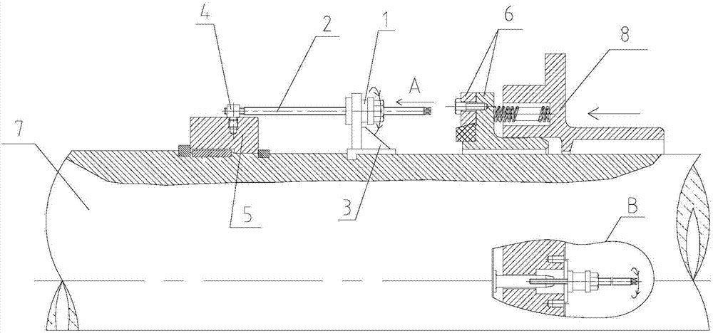
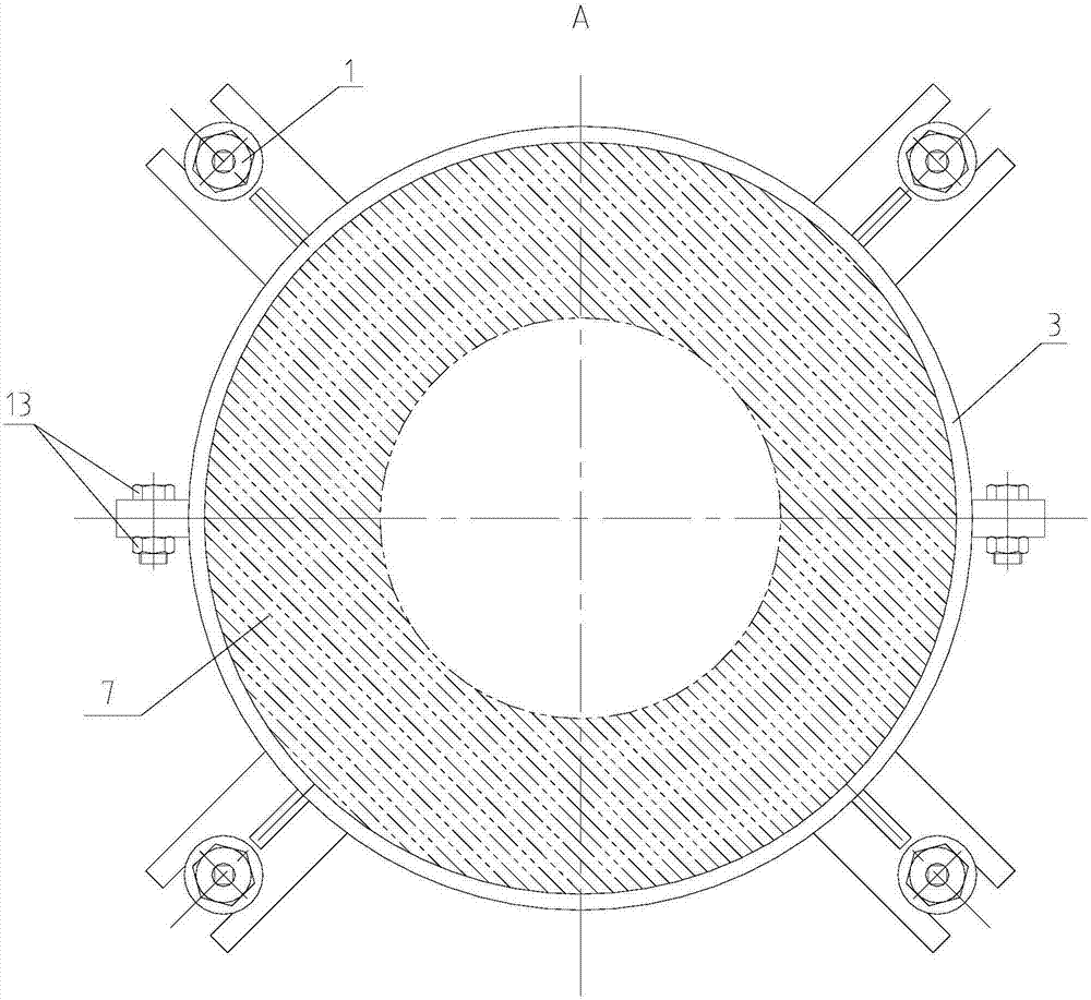
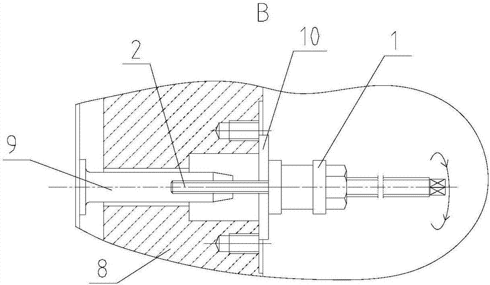
[0020] Such as figure 1 As shown, the present invention provides a synchronous disassembly and assembly device for the dynamic and static ring components of the stern shaft sealing device. A moving ring assembly 5, a static ring assembly 6, an end cover 8 and a main shaft 7;

[0021] Wherein, the threaded bush 1, screw rod 2, bracket 3 and earring 4 are used for the disassembly and assembly of the moving ring assembly 5, the threaded bush 1, the screw rod 2 and the washer are used for the disassembly and assembly of the static ring assembly 6, and the threaded bush and the screw rod can be It is generally used for the disassembly and assembly of dynamic and static ring components. When the moving ring assembly 5 is disassembled, the bracket 3 is axially fixed on the main shaft 7 in the form of two half rings, and the earrings are threadedly connected to ...


PUM


Abstract

The invention discloses a synchronous assembly and disassembly device for rotating and static ring components of a stern shaft sealing device. The synchronous assembly and disassembly device comprisesa threaded bushing, a support, lug rings, a screw, a pin and a gasket, and peripheral equipment comprises a rotating ring component, a static ring component, an end cap and a main shaft, wherein thesupport is formed in the way that two semi-rings are gathered and then fixed to the main shaft; the threaded bushing is axially limited by the lug rings; the screw is in threaded match with the innerhole of the threaded bushing; the lug rings are in threaded connection with the screw and the rotating ring component; a spring is mounted between the static ring component and the end cap; the pins sequentially penetrate the static ring component and the end cap; a threaded hole matched with the screw is formed in the front end of the pin; together with the threaded bushing, the screw penetratesthe gasket and then is connected with the pin; the screw is rotated to adjust the pre-tightening force between the static ring component and the end cap; and after the static ring component and the rotating ring component are in contact, the screw, the threaded bushing and the gasket are detached to finish assembly. The problem that a conventional stern shaft sealing device is difficult to mount and dismount due to pre-positioning of an electric compensation function can be solved.

Description

technical field [0001] The invention belongs to a disassembly and assembly device for a marine stern shaft seal device, in particular to a synchronous disassembly and assembly device for a dynamic ring assembly and a static ring assembly of a stern shaft seal device, which is used to meet the disassembly and assembly requirements of the stern shaft seal device after the elastic compensation function is pre-positioned . Background technique [0002] The marine stern shaft sealing device is a key sealing device to prevent outboard seawater from entering the cabin from the penetration of the stern shaft and the stern shaft hub. In the past ten years, various stern shaft sealing devices have been launched continuously. With the advantages of less leakage, long service life, and easy underwater maintenance, the outdated stuffing box seals have been gradually eliminated, and the technological progress of ship platforms has been promoted. However, because it works underwater, the ...

Claims


Application Information

Patent Timeline
Patent Type & Authority Applications(China)
IPC IPC(8): B25B27/00B25B27/02B63B9/00
CPCY02T70/00
Inventor 王隽王娟田佳彬张雪冰王刚伟何涛
Owner NO 719 RES INST CHINA SHIPBUILDING IND
Learn More