Sliding device, box corbel assembly component and method for installing box corbels with circular pipe column

A sliding device and sliding component technology, which is applied in the direction of manufacturing tools and hand-held tools, can solve the problems of complex assembly process, heavy construction, and difficult assembly, and achieve the effects of low labor intensity, cost reduction, and convenient assembly operation

Active Publication Date: 2020-05-22
KOCEL STEEL STRUCTURE CO LTD
View PDF4 Cites 0 Cited by
  • Summary
  • Abstract
  • Description
  • Claims
  • Application Information

AI Technical Summary

Problems solved by technology

[0002] The assembly process of the existing steel structure round pipe column with cross grooves to assemble box-shaped corbels is complicated and difficult to assemble. The construction has a large self-weight
[0003] Therefore, in this process, it is necessary to overcome the huge sliding friction force generated by large components, which brings great difficulties to assembly and low efficiency.

Method used


Image

  • Sliding device, box corbel assembly component and method for installing box corbels with circular pipe column
  • Sliding device, box corbel assembly component and method for installing box corbels with circular pipe column
  • Sliding device, box corbel assembly component and method for installing box corbels with circular pipe column

Examples


Embodiment 1

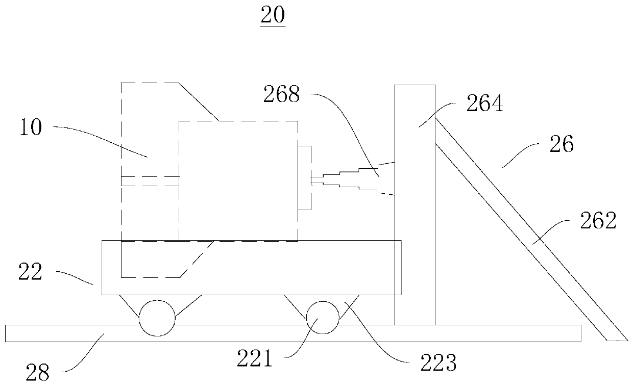
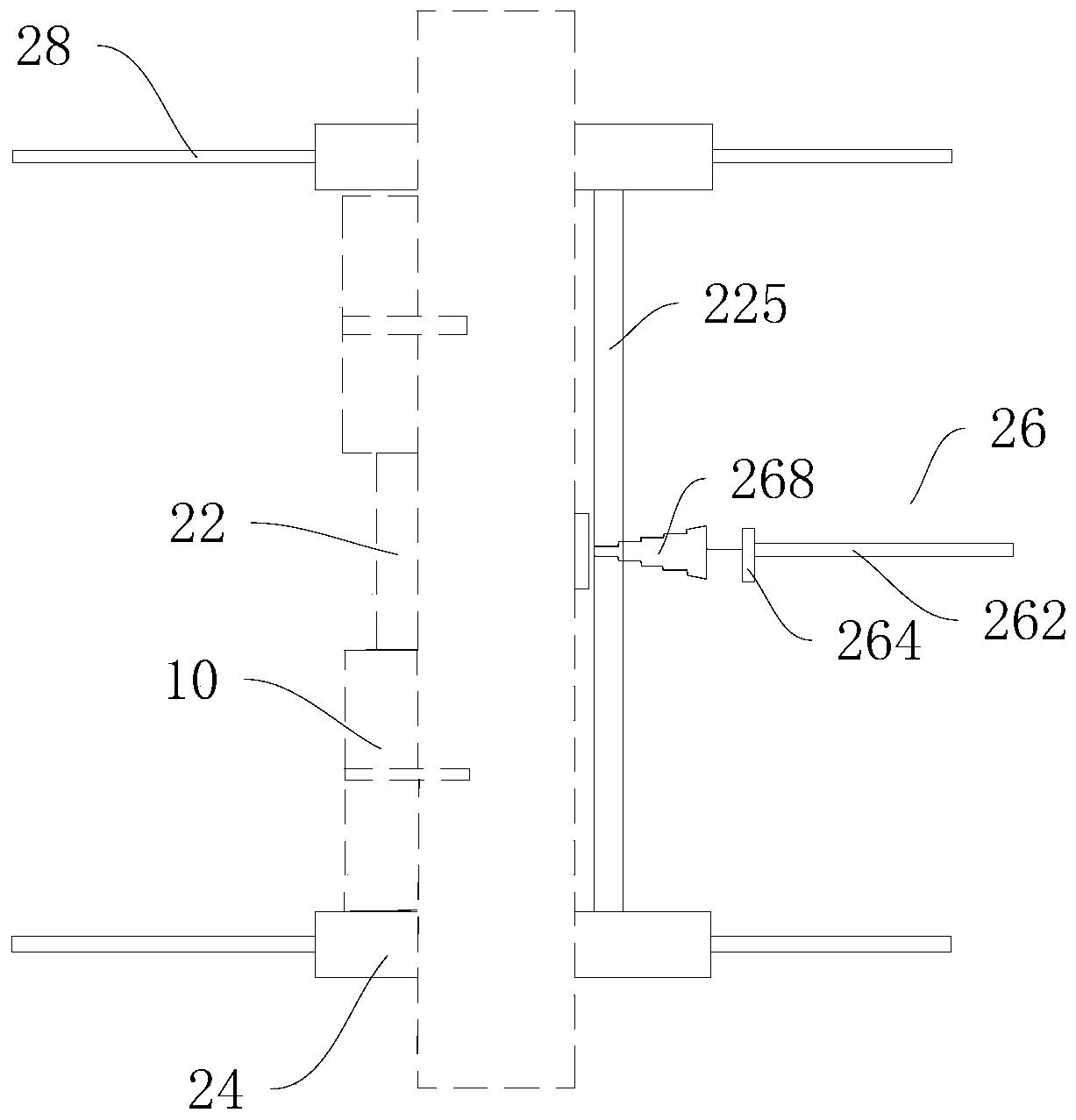
[0046] Such as figure 1 and figure 2 As shown, the sliding device 20 provided by Embodiment 1 of the present invention is used to assemble the box-shaped corbel 10 with the circular pipe column 15. Since the box-shaped corbel 10 is a box-shaped cross corbel, the end of the circular pipe column 15 is provided with The cross groove just matches the structure and size of the box-shaped cross corbel. The sliding device 20 includes a sliding assembly 22 , a supporting platform frame 24 , a positioning push assembly 26 and a slide rail 28 .

[0047] The specific structure of each component of the sliding device 20 and the corresponding relationship among them will be described in detail below.

[0048] Firstly, the slide assembly 22 is introduced in detail. The slide assembly 22 can slide back and forth along the slide rail 28 on the workbench to complete the assembly of the box-shaped corbel 10 and the round pipe column 15 arranged thereon. The specific structure is as follows. ...

Embodiment 2

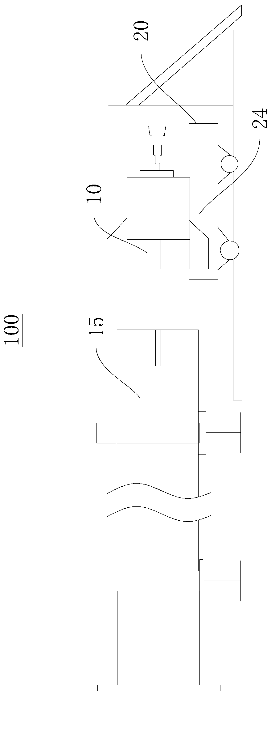
[0067] Embodiment 2 of the present invention provides a box-shaped corbel assembly assembly 100, including a box-shaped corbel 10 and the sliding device 20 provided in Embodiment 1. Please refer to image 3 and Figure 4 As shown, the specific description is as follows:

[0068] The box-shaped corbel 10 is a box-shaped cross corbel. First, the box-shaped corbel 10 is fixedly arranged on the support platform frame 24. Specifically, the box-shaped corbel 10 includes opposite cross fitting ends and abutting ends, wherein , the cross fitting end can cooperate with the cylindrical pipe column 15 , and the abutting end abuts against the positioning push assembly 26 .

[0069] Optionally, the round pipe column 15 is a steel structure round pipe column with a cross groove at its end, and its structure and size are just matched with the box-shaped corbel 10 .

[0070] By fixing the box-shaped corbel 10 on the support platform frame 24 of the sliding device 20, the movement of the box...

Embodiment 3

[0072] Embodiment 3 of the present invention provides a method for installing a box-shaped corbel 10 on a cylindrical column 15, using the sliding device 20 provided in Embodiment 1. The specific description is as follows:

[0073] The method for installing the box-shaped corbel 10 on the cylindrical column 15 includes:

[0074] Preparatory steps: positioning the round tube column 15 on the workbench, specifically, fixing the round tube column 15 on the workbench with a section steel limit, and the cross-groove end of the round tube column 15 can be elevated.

[0075] Leveling step: center and level the box-shaped corbel 10 set on the sliding device 20 and the round pipe column 15, specifically, set the slide rail 28 on the workbench correspondingly, and fix the box-shaped cross corbel on the sliding device 20 On the supporting platform frame 24, make the cross groove centering and leveling of the box type cross corbel and the round pipe column 15.

[0076] Assembly steps: op...


PUM


Abstract

The invention discloses a sliding device, a box-type beam stud assembly component, and a method for mounting a box-type beam stud in tubular pillars, and relates to the technical field of large-scalesteel-structure dual-tubular-pillar assembly. The sliding device comprises a sliding component, a supporting platform frame and a positioning-pushing component, wherein the sliding component can slideon a workbench; the supporting platform frame is fixedly arranged on one side of the sliding component; and the positioning-pushing component is fixedly arranged on the workbench and can be propped against the box-type beam stud, so that the box-type beam stud can be driven by the sliding component to slide and to be assembled with the tubular pillars. The box-type beam stud assembly component comprises the box-type beam stud and the sliding device, wherein the box-type beam stud is fixedly arranged on the supporting platform frame; the cross assembly end of the box-type beam stud can be matched with the tubular pillars; and the propping end of the box-type beam stud is propped against the positioning-pushing component. According to the sliding device and the box-type beam stud assembly component, the design is reasonable, the structure is simple, the assembly is convenient, the labor intensity is reduced, and the assembly work that cross grooves are formed in the two tubular pillarsfor the mounting of the box-type beam stud can be quickly and efficiently completed.

Description

technical field [0001] The invention relates to the technical field of assembly of large-scale steel structure double circular pipe columns, in particular to a sliding device, a box-shaped corbel assembly component and a method for installing a box-shaped corbel on a circular pipe column. Background technique [0002] The assembly process of the existing steel structure round pipe column with cross grooves to assemble box-shaped corbels is complicated and difficult to assemble. The self-weight of the construction is relatively large. [0003] Therefore, in this process, it is necessary to overcome the huge sliding friction force generated by large components, which brings great difficulties to assembly and low efficiency. [0004] To sum up, how to provide a simple device that can quickly and efficiently complete the assembly work of double cylindrical pipe columns with cross grooves and box-shaped corbels is a technical problem to be solved urgently by those skilled in the...

Claims


Application Information

Patent Timeline
Patent Type & Authority Patents(China)
IPC IPC(8): B25B27/02
Inventor 张昆冯剑罗正山
Owner KOCEL STEEL STRUCTURE CO LTD
Why Eureka
Try Eureka