Motor drive device with lock protection function

a technology of motor drive and function, which is applied in the direction of motor/generator/converter stopper, electronic commutator, dynamo-electric converter control, etc., can solve the problems of large amount of generated heat, risk of damaging the reliability of the device, and heat generated from an lsi leading to the thermo runaway of the lsi itself, etc., to achieve the effect of low power consumption and speedy operation

Active Publication Date: 2008-12-25
ROHM CO LTD
View PDF7 Cites 39 Cited by
  • Summary
  • Abstract
  • Description
  • Claims
  • Application Information

AI Technical Summary

Benefits of technology

[0014]According to this embodiment, in cases in which the control signal continues to instruct stoppage of the motor for at least the first time-period, the lock controller has the lock protection circuit inactive, so that it is possible to speed up restarting driving once again, after rotation of the motor is stopped by the instruction by the control signal. The control signal may be a pulse width modulation signal. The control signal may be a signal which adjusts duty ratio of this pulse width modulation signal.
[0015]Furthermore, after the second time-period has elapsed, since there is a transition to the standby mode, it is possible to realize low power consumption, and when there is a transition to the standby mode, since the lock protection circuit is inactive, when the motor is instructed to drive thereafter, rotation of the motor can be done speedily.

Problems solved by technology

In such LSIs, as the operational speed, that is, clock frequency, increases, amounts of generated heat become large.
There is a problem in that heat generated from an LSI leads to thermo runaway of the LSI itself, or has an effect on a surrounding circuit.
In a motor that drives the cooling fan, when the motor is locked by a foreign object being caught in the fan or the like, there is a risk of damaging device reliability by an excess current flowing in a coil or a semiconductor device.
That is, after the motor has been stopped by an instruction by the control signal, when a temperature rise of a device to be cooled is detected and the motor restarts rotation, a time lag until the start of rotation occurs, and there is a problem with temperature management.

Method used


Image

  • Motor drive device with lock protection function
  • Motor drive device with lock protection function
  • Motor drive device with lock protection function

Examples


Embodiment Construction

[0034]The invention will now be described based on preferred embodiments which do not intend to limit the scope of the present invention but exemplify the invention. All of the features and the combinations thereof described in the embodiment are not necessarily essential to the invention.

[0035]An embodiment relates to a cooling system which blows cool air by a fan, on an object to be cooled, such as, for example, an LSI or the like.

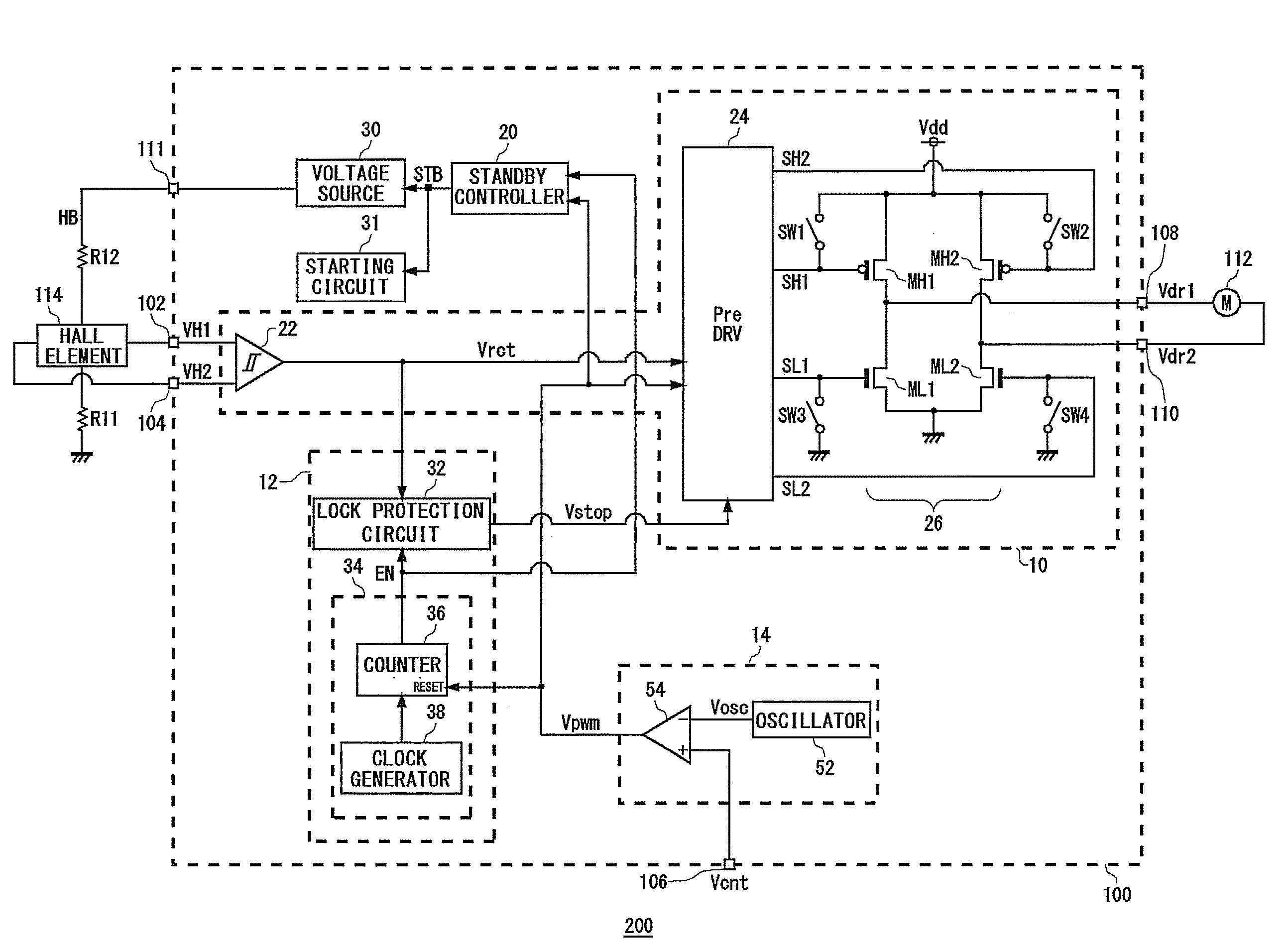
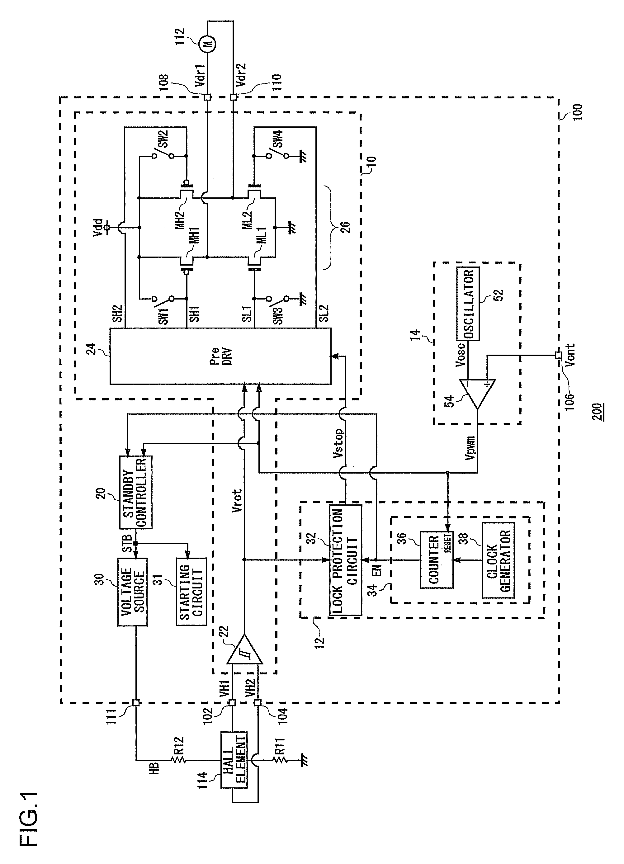
[0036]FIG. 1 shows a configuration of the cooling system 200 according to the embodiment.

[0037]The cooling system 200 is provided with a motor drive device 100, a fan motor 112, and a Hall element 114.

[0038]The fan motor 112 is a single-phase full-wave motor, and is arranged opposite the object to be cooled, which is not shown in the figure. In the fan motor 112, a coil current, that is, an energization state, is controlled by a drive voltage outputted from the motor drive device 100, and rotation is controlled.

[0039]A first terminal of the Hall element ...


PUM


Abstract

A cooling system is provided with a motor drive device, a fan motor, and a Hall element. The motor drive device includes a lock protection circuit and a lock controller. When a control signal instructing rotation of the fan motor that is to be driven instructs stoppage of the motor for a predetermined time-period or longer, the lock controller has the lock protection circuit inactive. At an occasion when the control signal has continued to instruct stoppage of the fan motor for a first time-period or longer, a standby controller starts time measurement, and after a further predetermined second time-period has elapsed, makes at least a part of the motor drive device transition to a standby mode.

Description

BACKGROUND OF THE INVENTION[0001]1. Field of the Invention[0002]The present invention relates to motor drive technology, and in particular, to a motor drive device provided with a lock protection function, a cooling system using the motor drive device, and a lock protection method.[0003]2. Description of the Related Art[0004]With the speeding up of personal computers and workstations in recent years, operation speeds are increasing steadily for computational LSIs (Large Scale Integrated circuits), such as in CPUs (Central Processor Units), DSPs (Digital Signal Processors) and the like.[0005]In such LSIs, as the operational speed, that is, clock frequency, increases, amounts of generated heat become large. There is a problem in that heat generated from an LSI leads to thermo runaway of the LSI itself, or has an effect on a surrounding circuit. Therefore, appropriate thermal cooling of the LSI is an extremely important technology.[0006]An example of a technology for cooling the LSI is...

Claims


Application Information

Patent Timeline
Patent Type & Authority Applications(United States)
IPC IPC(8): H02H7/085H02P3/08H02P6/06H02P6/08H02P6/12H02P6/26H02P7/29
CPCH02H7/0858H02H7/093H02P6/14H02P29/032
Inventor MISHIMA, TOMOFUMI
Owner ROHM CO LTD
Why Eureka
Try Eureka