Method for melting and decarburization of iron carbon melts

a technology of iron carbon melt and decarburization method, which is applied in the direction of lighting and heating apparatus, manufacturing converters, furnaces, etc., can solve the problems of limiting the amount of energy which can be introduced into the furnace and the rate at which it can be used efficiently, and the inability of the burner to deliver effective high-speed oxygen befor

Inactive Publication Date: 2004-06-15
PROCESS TECH INT
View PDF10 Cites 38 Cited by
  • Summary
  • Abstract
  • Description
  • Claims
  • Application Information

AI Technical Summary

Benefits of technology

According to one embodiment of the invention for steel making, the duration of the melting phase is decreased by adding increased amounts of energy early in the melting phase with the combustion products of a burner / lance flame which is directed into a more efficient combustion reaction zone, preferably below the refractory line of the furnace. When the burner flame is generated at this position of the furnace, several distinct advantages pertain to the steel making process. Melting a path for an injection of high velocity oxygen is facilitated because there is less path length to clear and it can be done faster. The time for melting the path length is further reduced by increasing the burner output to its maximum rating early in the melting phase. With a positioning of the flame below the refractory line, there is substantially less possibility for a flash back and the refractory can withstand such operation without catastrophic failure. The process of melting a clear path is also faster because the flame works in a hotter area closer to the electric arc. Further, the hot combustion gases flow upward through the total burden of scrap and cause additional energy transfer instead of heating the furnace atmosphere.
In addition to the efficiency gain caused by starting the oxidizing gas early in the melting cycle, a method for decarburization includes a process for increasing the efficiency of the oxidizing gas utilization in the iron carbon melt. More particularly, the method includes supplying a plurality of reaction zones with an oxidizing gas to decarburize an iron carbon melt with an efficient oxygen supply profile which is related to the carbon content of the melt. The multiple reaction zones are used to increase the amount of oxygen which can be effectively used for decarburization of the melt by increasing the reaction zone area and by making each reaction zone more efficient. Each reaction zone is more efficient because the surface dynamics of the process are occurring in multiple localized areas. The carbon being depleted in each local area is replenished more quickly than a single large area because of the better mass transport. This will lower the duration the decarburization process and at the same time oxidize less iron.
Preferably, after the critical carbon content has been reached, or optionally a carbon content near to the critical content below 0.2%, the multiple reaction zones can be supplied with reduced amounts of oxygen which are dependent upon the amount of carbon content at the particular time of the process. Preferably, the total oxygen supply profile for the multiple zones can approximate an exponential decay, similar to the demand for oxygen by the decreasing carbon content. Using multiple reaction zones during this phase of the decarburization process several distinct advantages. Because this phase of the decarburization process is dependent upon the surface reaction kinetics and carbon content, as the carbon content decreases, the multiple localized areas become even more efficient compared to a single reaction area. The increase in efficiency is greater because of the increased total reaction area and decreased time for the mass transport of the carbon in each zone. Further, multiple reaction zones combined with the shorter distance for the oxygen to travel to the molten metal in each zone creates several areas of deep penetration of the melt to increase agitation which is beneficial to the reaction.
Mounting the burner lance in a protective enclosure produces several advantages. The protective enclosure moves the burner flames and high velocity oxygen flow away from the wall of the furnace and closer to the edge of the refractory. This greatly reduces or eliminates the chance that the burner flames or the high velocity oxygen flow will reflect (flashback) against the furnace wall and create damage. Advantageously for the high velocity oxidizing gas flow, the flow has a shorter distance to travel to reach the melt compared to a lance mounted on the side wall. The shorter flow path length permits the oxidizing gas flow to impinge on the melt with a higher velocity and more concentrated flow pattern which causes a more efficient and rapid decarburization. The shorter flow path length also eliminates the need for excessive shrouding gasses and oxygen jets with large flow rates. This significantly reduces the negative oxidizing effects to the furnace because of excess oxygen.
Further, the shorter flow path length provided by the enclosure and multiple zones permitting reduced flow rates at each zone, allows the flow of the oxidizing gas at each zone to be controlled over a substantial range while still maintaining high velocity and efficient penetrating power for the melt at each zone. The capability of the preferred apparatus to permit the control of the oxidizing gas flow rate over a substantial range while still maintaining efficient decarburizing velocity facilitates the supply of an oxidizing gas profile to each reaction zone which is related to the carbon content of the melt.

Problems solved by technology

These burners can not deliver effective high velocity oxygen before then because unmelted scrap is in the way of the injection path and would deflect the oxygen flow.
Early in the melting phase a high velocity oxygen stream has no effective way to reach the iron carbon melt surface to penetrate it and decarburize the melt.
There are, however, practical considerations with conventional side wall mounted burners that limit the amount of energy which can be introduced into the furnace and the rate at which it can be used efficiently.
When scrap is initially loaded into the furnace, it is very near the flame face of the burner and the danger of a flash back of the flame against the side wall where it is mounted is significant.
Another problem to increasing the energy added during the early part of the melting phase is that the flame of the burner is initially directed to a small localized area of the scrap on the outside of the scrap burden.
It is difficult to transfer large amounts of energy of the burner from this localized impingement to the rest of the scrap efficiently.
Until the burner has melted the scrap away from its face and has opened a larger heat transfer area, increasing a burner to maximum output would only result in a substantial portion of the energy in the combustion gases heating the atmosphere.
However, as the bath carbon decreases to concentrations under approximately 0.15%-0.20% of carbon, it becomes increasingly difficult to achieve an acceptable rate.
At lower carbon levels, the iron oxide concentration in the slag reaches levels greater than equilibrium would allow, due to depleted local carbon concentration and poor mass transport.
This causes greater refractory erosion, loss of iron yield, increased requirements for alloys, and a low efficiency of oxygen utilization.
The conventional oxygen injection equipment that has been used for decarburization is not generally suited for efficient introduction of oxygen into an iron carbon melt.
The use of retractable consumable or water cooled lances through the slag door opening, or through the side wall, is always limited by the space available to position the equipment around the furnace.
Its location is usually only practical in the quadrant of the furnace shell near the slag door.
These large amounts of cold air reduce the efficiency of the process and also contribute to a nitrous oxide increase in the furnace atmosphere.
There is also a significant delay in moving the lance into the furnace through the scrap burden.
It is very difficult to deliver 100% of an oxygen stream effectively to a reaction zone at these distances.
Thus, increasing the bore size increases the total amount of effective oxygen reaching the iron carbon melt, but may also result in an increase of unused oxygen in the furnace atmosphere.
In spite of the effectiveness gained by shrouding, a significant amount of the oxygen is lost to the furnace environment causing several detrimental effects on operations.
Initially, there is the increased cost of the shrouding gases and specialized equipment to form the shroud.
The excess oxygen causes damage to the side wall panels, erosion of the shell refractory, development of excessive iron oxide in the slag, excessive electrode oxidation, reduction in the delta life, and may cause over heating of the furnace evacuation system.
Moreover, conventional oxygen injection equipment that has been used for decarburization is not generally suited to varying the oxygen supply rate over substantial ranges.
Fixed oxygen injection equipment such as burner / lances mounted on the side wall panels of the furnace have the problem that they are positioned some distance away from the surface of the iron carbon melt.
Further, the hot combustion gases flow upward through the total burden of scrap and cause additional energy transfer instead of heating the furnace atmosphere.

Method used


Image

  • Method for melting and decarburization of iron carbon melts
  • Method for melting and decarburization of iron carbon melts
  • Method for melting and decarburization of iron carbon melts

Examples


first embodiment

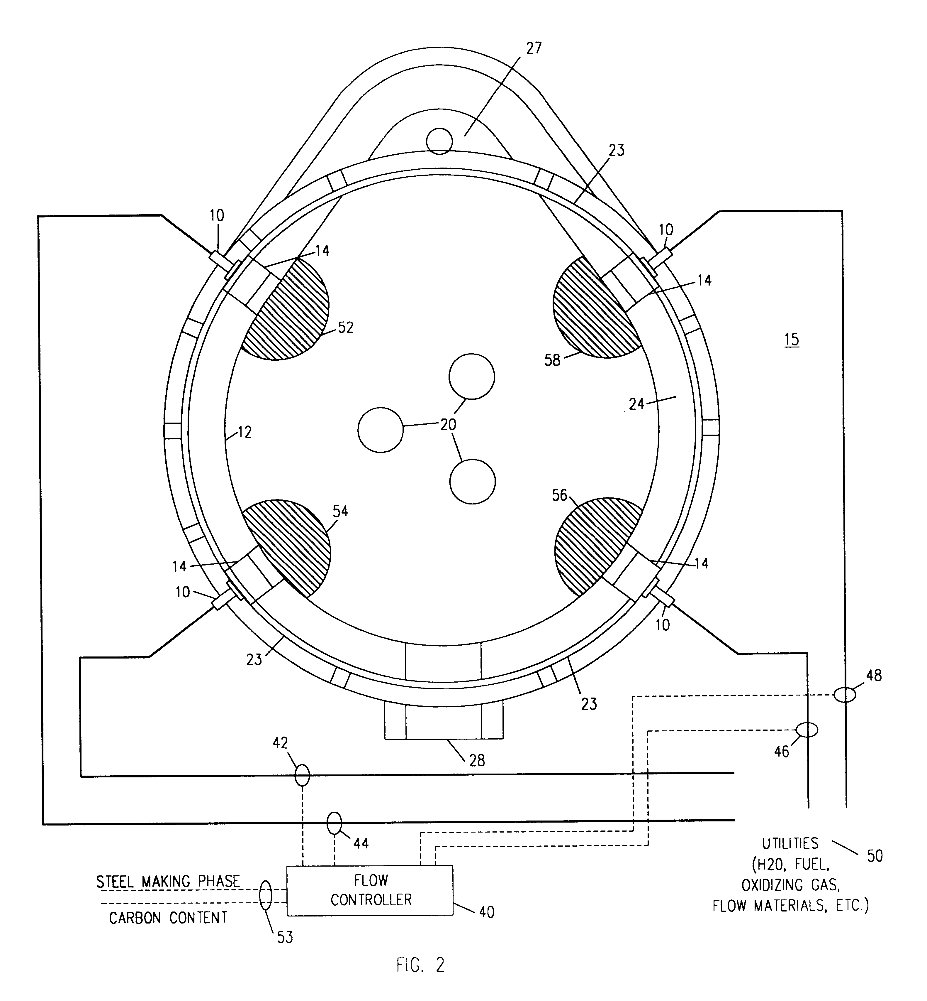
A first embodiment includes the controller 40 having a program which reduces the total oxygen supplied to the multiple reaction zones after the critical carbon content is reached by turning off one or more of the burner / lances 10 supplying oxygen to the individual reaction zones 52, 54, 56 and 58.

second embodiment

A second embodiment includes the controller 40 having a program which reduces the total amount of oxygen supplied to the multiple reaction zones after the critical carbon content is reached by varying the duty cycle of one or more of the burner / lances 10 supplying oxygen to the individual reaction zones 52, 54, 56 and 58. These control schemes advantageously allow the supply of oxygen to more closely follow the oxygen demand of the reaction after the critical content is reached. Moreover, they are particularly advantageous for oxidizing gas injection equipment where it is either inefficient or incapable to vary the flow rate.

A third preferred embodiment includes the controller 40 having a program which reduces the total amount of oxygen supplied to the multiple reaction zones after the critical carbon content is reached by combination of turning off or varying the duty cycle of one or more of the burner / lances 10 supplying oxygen to the individual reaction zones 52, 54, 56 and 58.

fourth embodiment

A fourth embodiment includes the controller 40 having a program which reduces the total amount of oxygen supplied to the multiple reaction zones after the critical carbon content is reached by varying the flow rate of one or more of the burner / lances 10 supplying oxygen to the individual reaction zones 52, 54, 56 and 58. This control scheme is most advantageously used with oxygen injection equipment with the capability of efficiently adjusting the high velocity oxidizing gas injection flow rates.


PUM

PropertyMeasurementUnit
injection angleaaaaaaaaaa
angleaaaaaaaaaa
angleaaaaaaaaaa

Abstract

A method and an apparatus for advantageously introducing a flame and a high velocity oxidizing gas into a furnace for metal melting, refining and processing, particularly steel making in an electric arc furnace. The steel making process of an electric arc furnace is made more efficient by shortening the time of the scrap melting phase and introducing an effective high velocity oxidizing gas stream into the process sooner to decarburize the melted metal. In one implementation of an apparatus, improved efficiency is obtained by mounting a fixed burner / lance closer to the hot face of the furnace refractory at an effective injection angle. This mounting technique shortens the distance that the flame of the burner has to melt through the scrap to clear a path to the molten metal and shortens the distance the high velocity oxygen from the lance travels to the slag-metal interface thereby increasing its penetrating power. The method additionally includes supplying a plurality of reaction zones with the high velocity oxidizing gas to decarburize the melted metal. The plurality of reaction zones increases the surface area available for the reaction thereby allowing a more rapid rate of decarburization and a more homogenous metal bath. The reaction zones are supplied with the high velocity oxidizing gas according to an oxygen supply profile which is related to the carbon content of the metal bath. In this manner an optimal amount of oxygen can be introduced into the metal bath to shorten the decarburization process without producing excessive oxidation of the metal bath and excessive free oxygen in the furnace.

Description

1. Field of the InventionThe present invention generally relates to a method and apparatus used in metal melting, refining and processing, for example, steel making in an electric arc furnace (EAF), and more particularly, to a method and apparatus for the melting and decarburization of an iron carbon melt.2. Description of Background ArtAn electric arc furnaces (EAFs) make steel by using an electric arc to melt one or more charges of scrap metal which is placed within the furnace. Modem EAFs also make steel by melting DRI (direct reduced iron) combined with the hot metal from a blast furnace. In addition to the electrical energy of the arc, chemical energy is provided by auxiliary burners using fuel and an oxidizing gas to produce combustion products with a high heat content to assist the arc.If the EAF is used a scrap melter, the scrap burden is charged by dumping it into the furnace through the roof opening from buckets which also may include charged carbon and slag forming materi...

Claims


Application Information

Patent Timeline
Patent Type & Authority Patents(United States)
IPC IPC(8): C21C5/00C21C5/46C21C5/52F27D1/12H05B7/00H05B7/18F27B3/22F27B3/20F27B3/10F27D9/00
CPCC21C5/462C21C5/5217F27D1/12H05B7/185F27B3/205F27B3/225F27D2009/0045Y02P10/20
Inventor SHVER, VALERY G.
Owner PROCESS TECH INT
Why Eureka
Try Eureka