Convective vacuum phase change heat sink LED lamp

A LED lamp and phase change technology, applied in lighting and heating equipment, cleaning methods and utensils, semiconductor devices of light-emitting elements, etc., can solve the problems of LED lamp maintenance, reduce the service life of LED lamps, increase the workload of workers, etc., to achieve Effects of prolonging life, expanding irradiation area, and facilitating maintenance

Inactive Publication Date: 2018-01-12
惠勇
View PDF0 Cites 2 Cited by
  • Summary
  • Abstract
  • Description
  • Claims
  • Application Information

AI Technical Summary

Problems solved by technology

[0003] LED lights are widely used in various fields. LED lights in factory workshops are often set at high places, which is inconvenient to maintain LED lights and reduces the service life of LED lights. When LED lights need to be replaced, workers need to climb Going to a high place to replace, on the one hand, increases the workload of workers, and on the other hand, increases the danger of workers replacing LED lights. In the workshop, the angle of the inclined feet of the LED lights is fixed, and only one area can be illuminated, reducing the LED lights. Work flexibility, the air in the workshop contains a lot of charged particles, these charged particles are easily adsorbed on the glass cover at the front of the LED lamp, after a long time, the charged particles on the glass cover will absorb too much, reducing the light of the LED lamp strength

Method used


Image

  • Convective vacuum phase change heat sink LED lamp
  • Convective vacuum phase change heat sink LED lamp
  • Convective vacuum phase change heat sink LED lamp

Examples


specific Embodiment approach

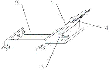
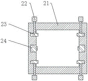
[0029] Specific embodiments: when using the present invention, the staff first starts the motor one 22, the motor one 22 works to drive the roller 23 to rotate, the annular fixed ring 21 moves upward under the action of the roller 23, and the upward movement of the annular fixed frame 21 drives the fixed plate 31 upward Moving, the fixed plate 31 moves upward to drive the support rod 1 32 and the support rod 2 37 to move upward, and then drives the LED lamp main body 1 to move upward until the LED lamp main body 1 reaches a suitable height, the staff turns off the motor 1 22, and then the staff starts The electric telescopic rod one 24, the electric telescopic rod one 24 works to drive the connecting rod to move inward, fix the annular fixing ring 21 and the square support column, and then fix the position of the LED lamp main body 1, this design facilitates the movement and fixing of the LED lamp main body 1 .

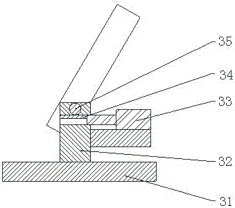
[0030] The staff starts the electric telescopic rod 2 33, and th...


PUM


Abstract

The present invention provides a convective vacuum phase change heat sink LED lamp comprising a support rod I, an electric retractable rod II, a rack, a gear, a rotating shaft, a support rod II, a motor II, a fixed block, an outer rod, an electric retractable rod III and an inner rod. The support rod II is arranged behind the support rod I. The electric retractable rod II is mounted at the right end of the support rod I. The rack is mounted at the left end of the electric retractable rod II. The gear is mounted at the upper end of the rack. The rotating shaft is arranged at the rear end of thegear. The support rod I is arranged at the front end of the rotating shaft and the support rod II is arranged at the rear end of the rotating shaft. Such a design is convenient for adjusting the inclination angle of the main body of the LED lamp. Furthermore, the motor II is arranged at the left end of the fixed block. The outer rod is mounted at the right end of the motor II, and the outer rod is arranged at the right end of the fixed block. The inner rod is arranged at the rear end of the outer rod. The electric retractable rod is mounted at the front end of the inner rod and arranged within the outer rod. Such a design is convenient for cleaning the main body of the LED lamp body. The convective vacuum phase change heat sink LED lamp is convenient to use, convenient to maintain, convenient to clean and good in flexibility.

Description

technical field [0001] The invention is a convective vacuum phase-change heat dissipation LED lamp, which belongs to the field of LED lamp equipment. Background technique [0002] LED is the abbreviation of light-emitting diode in English. Its basic structure is an electroluminescent semiconductor material chip, which is cured on the bracket with silver glue or white glue, and then connected to the chip and circuit board with silver or gold wires, and then surrounded by It is sealed with epoxy resin to protect the inner core wire, and finally the shell is installed, so the LED lamp has good shock resistance. The application field involves mobile phones, table lamps, home appliances and other daily household appliances and mechanical production. [0003] LED lights are widely used in various fields. LED lights in factory workshops are often set at high places, which is inconvenient to maintain LED lights and reduces the service life of LED lights. When LED lights need to be r...

Claims


Application Information

Patent Timeline
Patent Type & Authority Applications(China)
IPC IPC(8): F21S8/00F21V21/36F21V21/22F21V21/15F21V21/30B08B1/00F21Y115/10
Inventor 惠勇
Owner 惠勇
Why Eureka
Try Eureka