

Furnace burden drying device
A technology of drying device and charge, applied in the directions of drying, dryer, drying gas arrangement, etc., can solve the problems of uneven drying and heating of charge, and achieve the effects of improving capacity, speeding up discharge speed and improving work efficiency.
Active Publication Date: 2018-01-12
重庆琅博宛冶金材料有限公司
View PDF6 Cites 7 Cited by
- Summary
- Abstract
- Description
- Claims
- Application Information
AI Technical Summary
Problems solved by technology
[0004] The object of the present invention is to provide a furnace charge drying device to solve the problem of uneven drying and heating of the furnace charge
Method used
View moreImage
Smart ImageViewing Examples

Examples
Embodiment Construction
[0017] Below in conjunction with accompanying drawing and specific embodiment the present invention will be described in further detail:
Login to View More PUM
 Abstract
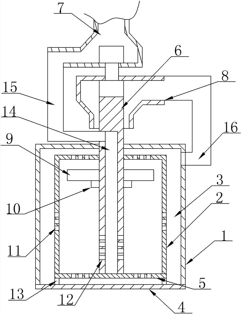
The invention relates to the technical field of metallurgical furnace burden, and discloses a furnace burden drying device. The furnace burden drying device comprises a rack, an inner furnace body, anouter furnace body, an air blower and a turbocharger. The outer furnace body is fixedly mounted on the rack, the outer furnace body is arranged on the outer side of the inner furnace body in a sleeving mode, and a flowing cavity is formed between the inner furnace body and the outer furnace body. The inner furnace body is fixedly mounted on the outer furnace body, air vents communicating with theflowing cavity are formed in the side wall and the upper portion of the inner furnace body, a rotary shaft fixedly connected with a turbine of the turbocharger is arranged in the inner furnace body,and the rotary shaft is rotatably connected with the inner furnace body. A spiral electric coil for heating is fixed to the interior of the side wall of each of the inner furnace body and the rotary shaft, an air inlet of a compression wheel of the turbocharger communicates with an air outlet of the air blower, and a turbine air suction port of the turbocharger communicates with the flowing cavity. The furnace burden drying device can dry furnace burden evenly, and can rapidly treat the moisture generated in the drying process of the furnace burden, the working efficiency is improved, and thequality of the furnace burden is improved.
Description
technical field [0001] The invention relates to the technical field of metallurgical charge, in particular to a charge drying device. Background technique [0002] In the production process, the charge is baked at high temperature to improve the strength of the charge product. The existing drying box has a single function, which is not conducive to the baking of the charge product. In the prior art, in order to discharge the moisture evaporated from the charge, an air outlet is set on the top of the oven, and an air exhauster is connected to the air outlet to extract the moisture. However, this arrangement makes the moisture near the air outlet easy to be sucked out gas, and the moisture far away from the air outlet is not easy to discharge. The accumulation of moisture in some areas has a greater impact on the quality of the furnace charge in this part, and the wind speed at the air outlet is faster, resulting in a lower temperature in this area, which affects the The heat...
Claims
Login to View More Application Information
Patent Timeline
 IPC IPC(8): F26B11/16F26B21/00F26B25/00F26B25/04
Inventor胡丰强
Owner重庆琅博宛冶金材料有限公司