Dynamic crack tip stress field measuring method and device

A crack tip and stress field technology, applied in the field of stress field experimental research, can solve problems such as the influence of manual proficiency, the accuracy of measurement results, and complex operations

Active Publication Date: 2018-01-12
CHINA UNIV OF MINING & TECH (BEIJING)
View PDF4 Cites 18 Cited by
  • Summary
  • Abstract
  • Description
  • Claims
  • Application Information

AI Technical Summary

Problems solved by technology

However, this method is complicated to operate, and the sticking of strain gauges is affected by manual proficiency, which will affect the accuracy of measurement results
[0003] Existing mechanical methods of optical measurement, such as holographic interferometry, photoelasticity, and moiré interferometry, can visually display the deformation information on the surface of the test object. However, this type of measurement method needs to be carried out in a darkroom environment during the experiment. Moreover, vibration isolation is required, and the accuracy of its measurement results is easily affected by the external environment

Method used


Image

  • Dynamic crack tip stress field measuring method and device
  • Dynamic crack tip stress field measuring method and device

Examples


Embodiment 1

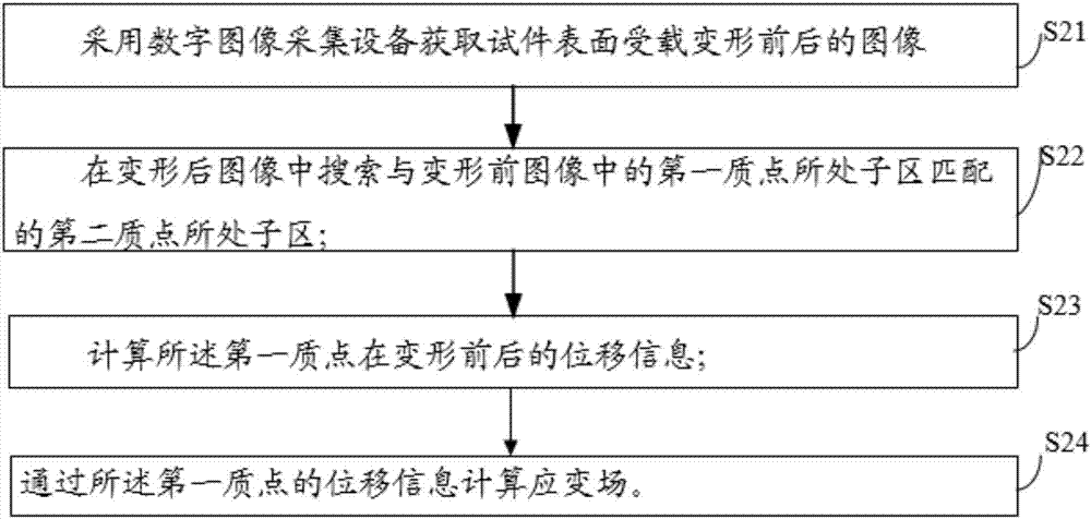
[0054] see figure 1 As shown, the embodiment of the present invention is a dynamic crack tip stress field measurement method, which can be applied to the measurement of various stress fields including the dynamic crack tip, including steps: S1, using digital image acquisition equipment to obtain the test piece surface affected Loading images before and after deformation; S2, searching in the post-deformation image for a sub-area where the second mass point is located that matches the sub-area where the first mass point is located in the image before deformation; S3, calculating the displacement information of the first mass point before and after deformation; S4. Calculate the stress field according to the displacement information of the first mass point.

[0055] An embodiment of the present invention is a method for measuring the stress field at the tip of a dynamic crack. By searching the deformed image for the sub-area where the second mass point is located that matches th...

Embodiment 2

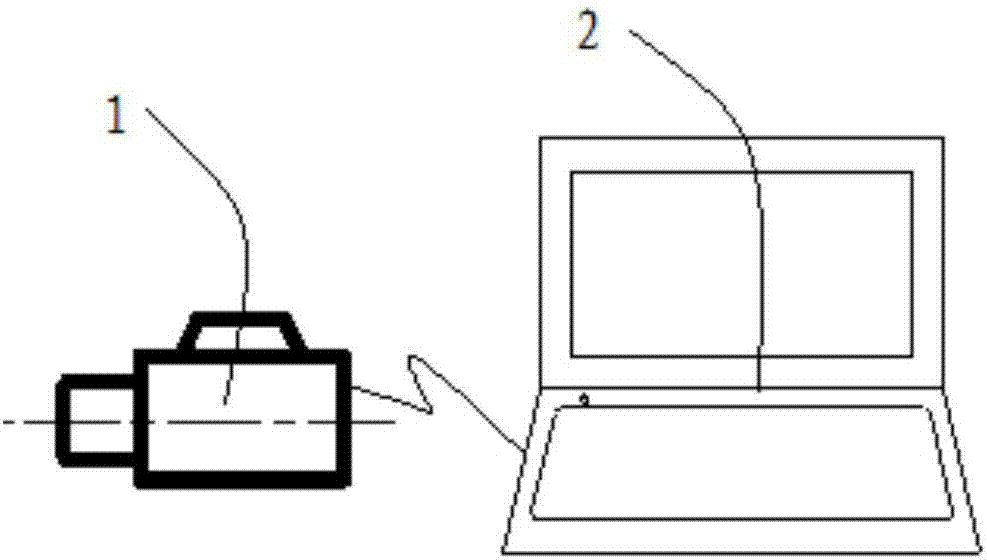
[0062] see figure 2 As shown, the embodiment of the present invention provides a dynamic crack tip stress field measurement system, including: an image acquisition device 1 and a digital image processing device 2; Converting the image into a digital signal and sending it to the digital image processing device; the digital image processing device is used to search for a sub-region where the first particle is located in the image after deformation that matches the sub-region where the first particle is located in the image before deformation. area; calculating the displacement information of the first mass point before and after deformation; calculating the stress field through the displacement information of the first mass point.

[0063] In the measurement system described in this embodiment, since the image processing device searches the deformed image for the sub-area where the second mass point is located that matches the subsystem where the first displaced mass point is l...


PUM


Abstract

An embodiment of the invention disclose a dynamic crack tip stress field measuring method and a dynamic crack tip stress field measuring device, which relate to the technical field of stress field experimental research. The dynamic crack tip stress field measuring method comprises the steps of: using digital image acquisition equipment to acquire images before and after the surface of a test specimen deforms after being loaded; searching for a sub-region in which a second mass point locates in the image after deformation, wherein the sub-region in which the second mass point locates is matchedwith a sub-region in which a first mass point locates in the image before deformation; calculating displacement information of the first mass point before and after deformation; and calculating a stress field according to the displacement information of the first mass point. The dynamic crack tip stress field measuring method and the dynamic crack tip stress field measuring device are applicableto crack detection and mechanical laboratory.

Description

technical field [0001] The invention relates to the technical field of stress field experimental research, in particular to a method and device for measuring a dynamic crack tip stress field. Background technique [0002] Scholars at home and abroad have proposed many experimental methods and theories in the research field of stress field distribution and expansion mechanism around dynamic cracks. Classical experimental mechanics methods include strain electrometry and photometry. The basic principle of the strain electrical measurement method is to measure the linear strain on the surface of the component with the resistance strain gauge, and then determine the stress state of the surface of the component according to the strain-stress relationship. This method belongs to the contact measurement method. Specifically, the resistance strain gauge is pasted on the surface of the measured component. When the component is deformed, the resistance value of the resistance strain ...

Claims


Application Information

Patent Timeline
Patent Type & Authority Applications(China)
IPC IPC(8): G01L5/00G01N21/95
Inventor 王雁冰
Owner CHINA UNIV OF MINING & TECH (BEIJING)
Why Eureka
Try Eureka