Ultrasonic diagnostic system

a diagnostic system and ultrasonic technology, applied in the field of ultrasonic diagnostic systems, can solve problems such as scale and cost, radiation exposure, and inability to improve the reliability of measurement, and achieve the effects of high precision, reliable measurement results, and superior reproducibility

a diagnostic system and ultrasonic technology, applied in the field of ultrasonic diagnostic systems, can solve problems such as scale and cost, radiation exposure, and inability to improve the reliability of measurement, and achieve the effects of high precision, reliable measurement results, and superior reproducibility

US20120215109A1Inactive Publication Date: 2012-08-23THE UNIV OF TOKYO +1

Image

  • Ultrasonic diagnostic system
  • Ultrasonic diagnostic system
  • Ultrasonic diagnostic system

Examples


Embodiment Construction

[0047]A preferred embodiment of the present invention will now be described with reference to the drawings.

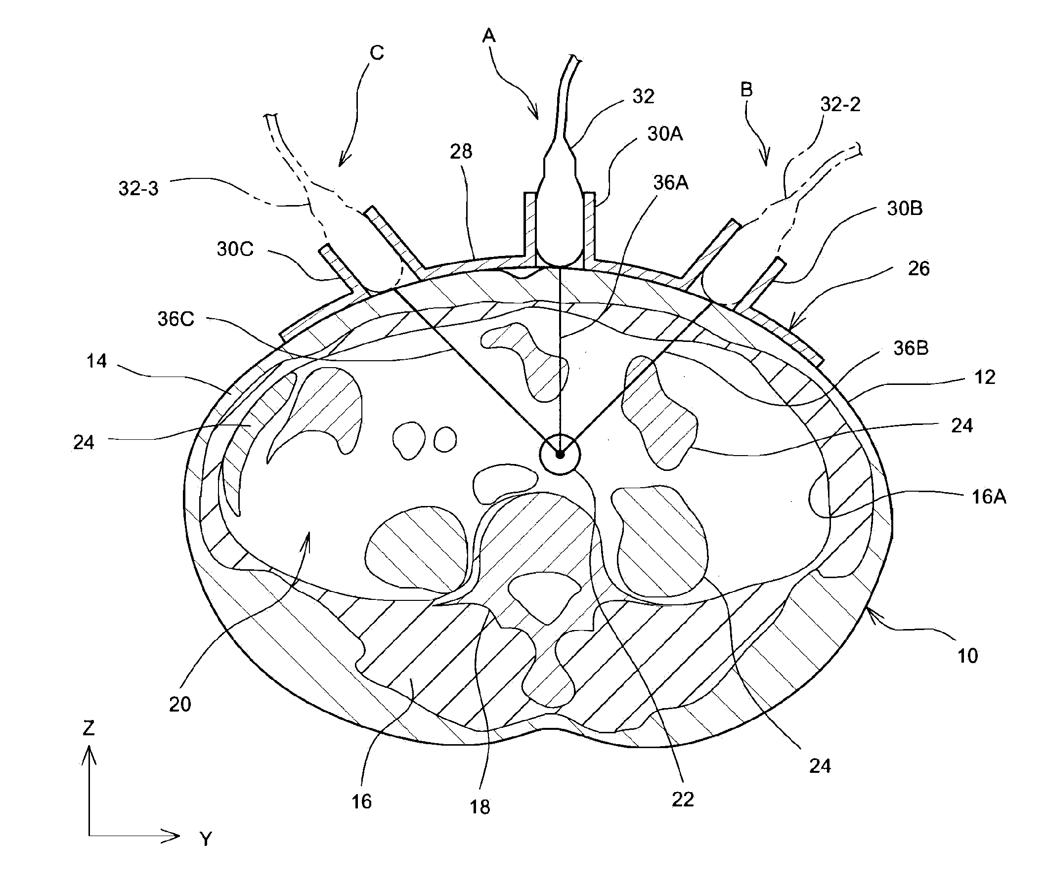
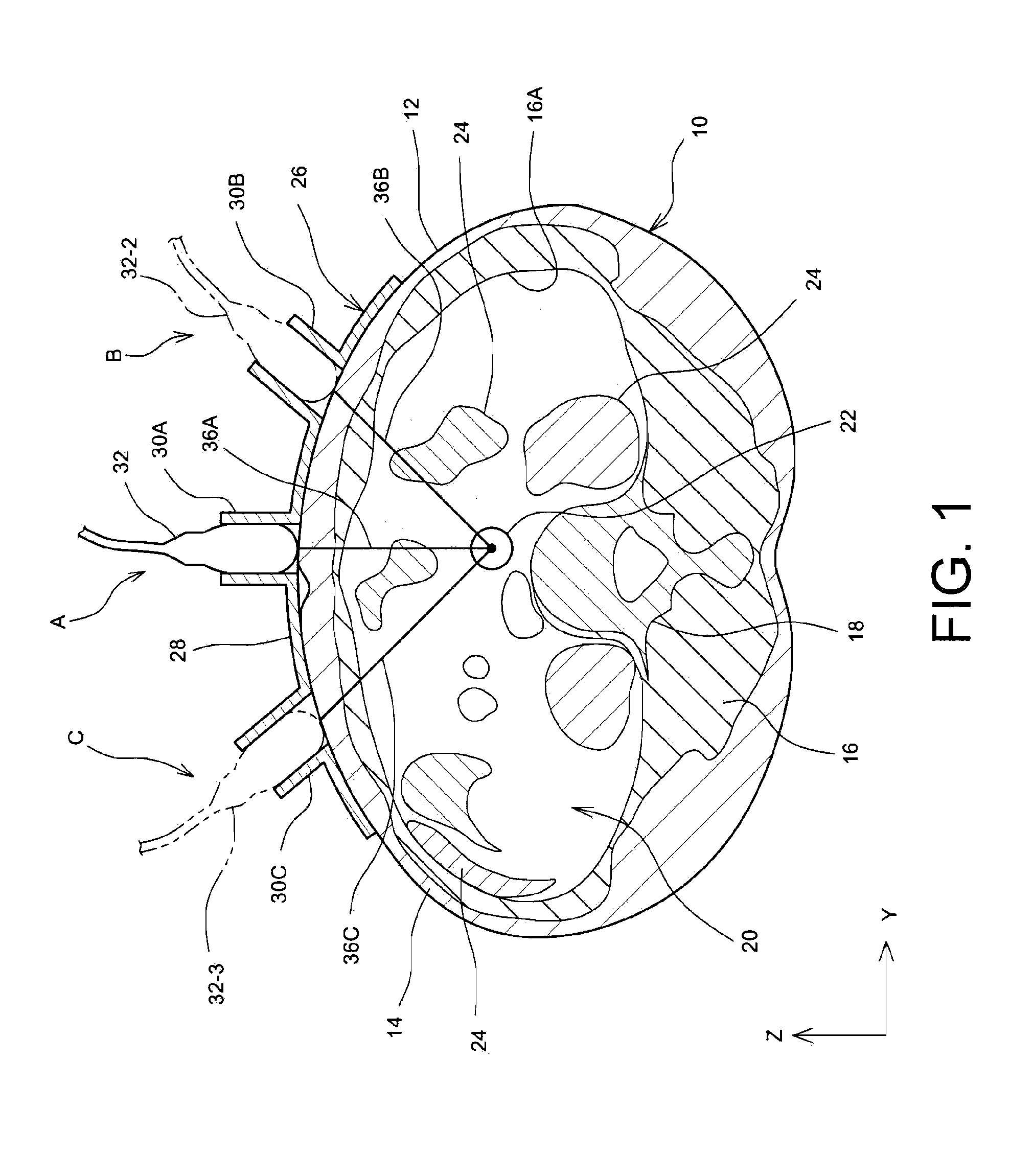
[0048]FIG. 1 schematically shows a lateral cross section of an abdominal region of a living body. FIG. 1 particularly shows a situation where an index value having a correlation to the amount of visceral fat is measured and calculated. An X direction is a direction of the spine, a Z direction is a direction of thickness of the living body, and a Y direction is a left-and-right direction. The lateral cross section of FIG. 1 is a cross section which is observed by setting a viewing line from a leg side toward a head side.

[0049]In FIG. 1, reference numeral 10 represents an abdominal region of the living body, with a lower side of the abdominal region 10 representing the back and an upper side of the abdominal region 10 representing a surface 12 of the abdominal region 10. For example, the living body is placed on a bed facing upward. In the inside of the abdominal region 10, a sub...


PUM


Abstract

When an amount of visceral fat is measured using ultrasonic waves during medical examination of metabolic syndrome, three contact positions are defined on the surface of the abdominal region, and three distances inside the living body are measured by bringing a probe into contact with the surface of the abdominal region at the contact positions. Specifically, three measurement paths having a starting point at the center of the descending aorta are set, and the distances from the center to a surface of the fat layer adjacent to the surface of the body (inner surface of the subcutaneous layer) in the measurement paths are observed. An approximate area of a visceral fat region can be determined from the three distances and two angles defined by the three measurement paths, and an index value is calculated on the basis of the area. A probe holder having three holding portions is desirably used.

Description

TECHNICAL FIELD[0001]The present invention relates to an ultrasonic diagnostic system, and in particular to an ultrasonic diagnostic system which measures visceral fat.BACKGROUND ART[0002]In the medical field, ultrasonic diagnostic systems are being utilized. An ultrasonic diagnostic system is generally formed from an ultrasonic diagnostic device or from a combination of an ultrasonic diagnostic device and a computer. The ultrasonic diagnostic device comprises an ultrasonic probe which transmits ultrasound to a living body and receives a reflected wave from the living body, and a device body which executes image formation and various measurements based on the received signal from the ultrasonic probe. With the ultrasonic diagnosis, it is possible to avoid a problem occurring in X-ray diagnosis such as radiation exposure, and the ultrasonic diagnosis does not require a large-scale device such as that required for X-ray diagnosis. Because of such convenience, it is desired to apply th...

Claims


Application Information

Patent Timeline
23 Aug 2012
Publication
US20120215109A1
IPC
A61B8/14; A61B5/107
CPC
A61B5/4872; A61B8/085; A61B8/0858; A61B8/5223; A61B8/4209; A61B8/4227; A61B8/14; G16H50/30
Inventors
KUBOTA, NAOTO; KOIZUMI, NORIHIRO