Eureka AIR delivers breakthrough ideas for toughest innovation challenges, trusted by R&D personnel around the world.

Roller component of leather buffing machine

A technology of a dermabrasion machine and a roller is applied in the field of leather processing, which can solve the problems of wasting the time of R&D personnel, inconvenient for leather development and research, and unreachable leather samples.

Inactive Publication Date: 2018-01-16
WENZHOU POLYTECHNIC
View PDF4 Cites 0 Cited by
  • Summary
  • Abstract
  • Description
  • Claims
  • Application Information

AI Technical Summary

Problems solved by technology

[0004] The development of leather is also changing with each passing day. When developing new types of leather, it is often necessary to polish the leather by hand, while ordinary grinding machines are used in assembly lines, and the equipment is relatively large. If it needs to be used to develop new leather, it will be necessary Mechanical re-adjustment is extremely inconvenient for the development and research of leather. Manual polishing requires a lot of time for R&D personnel, resulting in low R&D efficiency, and the leather samples that are manually polished often do not meet the required requirements.

Method used


Image

  • Roller component of leather buffing machine
  • Roller component of leather buffing machine

Examples


Embodiment Construction

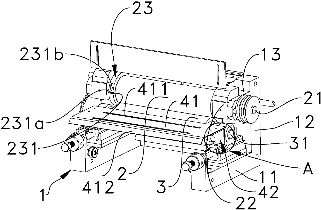
[0016] Specific embodiments of the present invention such as Figure 1-2 Shown is the roller assembly of the leather dermabrasion machine, including the support base 1 arranged on the workbench. The upper roller 2 assembly and the lower roller 3 assembly are erected on the support base 1. Between the upper and lower roller 3 assemblies There is a gap channel for the leather to pass through. The upper roller 2 assembly includes the upper roller connecting shaft 21 and the upper roller 2 sleeved outside the upper roller connecting shaft 21. The two ends of the upper roller connecting shaft 21 protrude Outside the upper roller 2 and installed on the upper roller seat 22, the outer circumference of one end of the upper roller 2 is sleeved with a clamping sleeve 23. The clamping sleeve 23 is an opening structure 231, and one radial end surface of the opening structure 231 A locking screw hole 231a is provided, and the other side of the opening structure 231 is provided with a throu...


PUM


Abstract

The invention discloses a roller component of a leather buffing machine. The roller component comprises a supporting seat arranged on an operating platform, wherein upper and lower roller components are arranged on the supporting seat; a gap channel is formed between the two roller components; the lower roller component comprises a lower roller connecting shaft and a lower roller; the two ends ofthe lower roller connecting shaft extend out of the lower roller and are mounted on a shaft end seat; a saddle is fixedly mounted on the shaft end seat; the saddle is positioned at the front end of the lower roller; the surface of the saddle is parallel to the bottom surface of the gap channel; the upper roller component comprises an upper roller connecting shaft and an upper roller; the two endsof the upper roller connecting shaft extend out of the upper roller and are mounted on an upper roller seat; a clamping sleeve body is connected with one end of the upper roller in a sleeving manner;the clamping sleeve body adopts an opening structure; a locking screw hole is formed in the radial end surface on one side of the opening structure; a through hole corresponding to the locking screw hole is formed in the other side of the opening structure; a locking screw which can penetrate through the through hole and is matched with the locking screw hole is matched with the through hole. Theroller component has a firm structure, can be finely adjusted to meet the buffing requirements of leather with different demands.

Description

technical field [0001] The invention belongs to the technical field of leather processing, in particular to a roller assembly of a leather buffing machine. Background technique [0002] The leather industry covers the main industries such as tanning, shoemaking, leather clothing, leather goods, fur and its products, and promotes the development of supporting industries such as leather chemicals, leather hardware, leather machinery, and accessories. [0003] China's leather industry, after adjusting and optimizing its structure, has initially formed a number of leather production characteristic areas and professional markets throughout the country with clear division of labor, outstanding characteristics, and playing a decisive role in stimulating the local economy. Their formation has laid the foundation for the development of China's leather industry. In an increasingly competitive market environment, it is not easy for China's leather industry to achieve such achievements...

Claims


Application Information

Patent Timeline
IPC IPC(8): C14B1/44C14B17/02C14B17/06
Inventor 金花
Owner WENZHOU POLYTECHNIC
Why Eureka
Eureka Blog
Learn More