

Doorknob structure
A technology for door handles and handles, which can be applied to handle connections, door/window accessories, building structures, etc. It can solve the problems that door locks cannot be used for both left-handed and right-handed doors at the same time, repurchase is appropriate, and replacement costs, etc.
- Summary
- Abstract
- Description
- Claims
- Application Information
AI Technical Summary
Problems solved by technology
Method used
Image

Examples
Embodiment
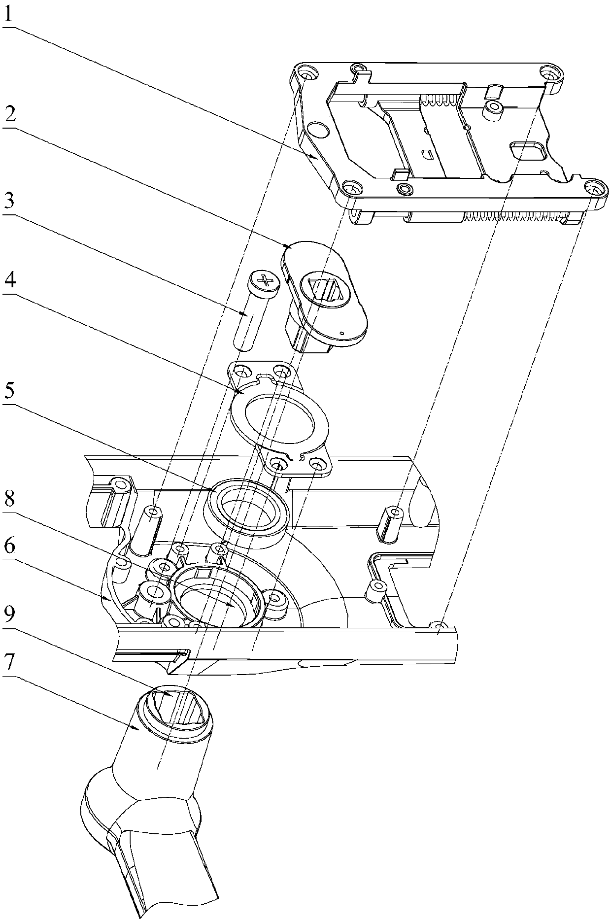
[0046] refer to Figure 1 to Figure 14 , a door handle structure, which includes a panel 6; a handle 7, one side passing through the panel 6 is provided with a handle turning block 2;
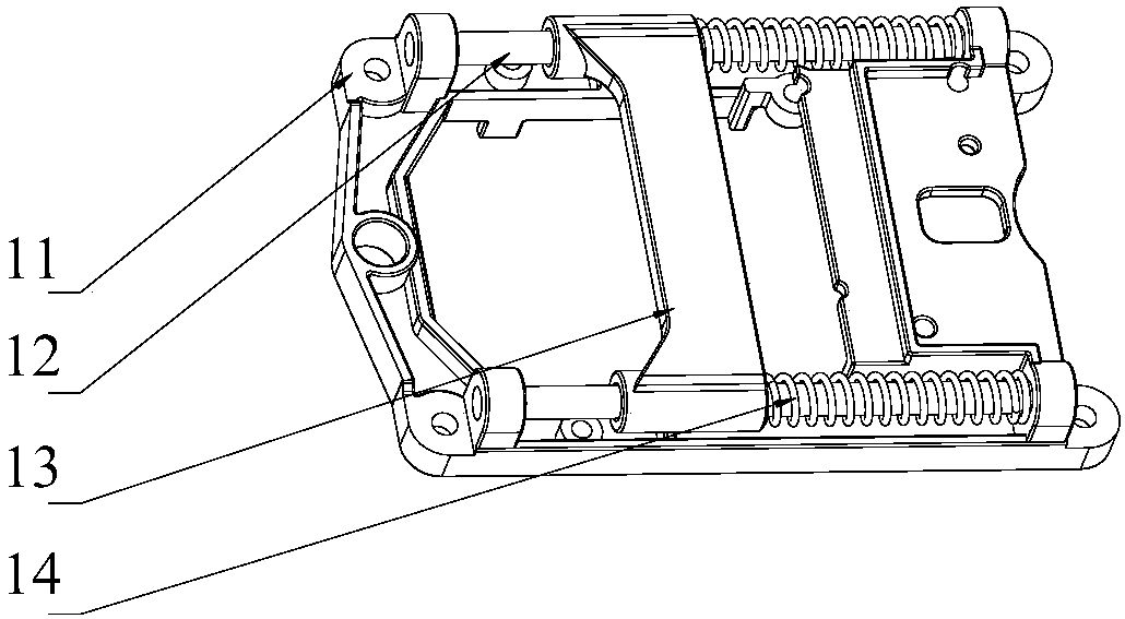
[0047] The handle spring seat 11 is provided with a guide post 12, and the guide post 12 is provided with an elastic member; the elastic member is preferably a spring 14 or a rubber ring.
[0048] The slider 13 is rotated by the handle block 2 to drive the slider 13 to move back and forth along the guide column 12 .
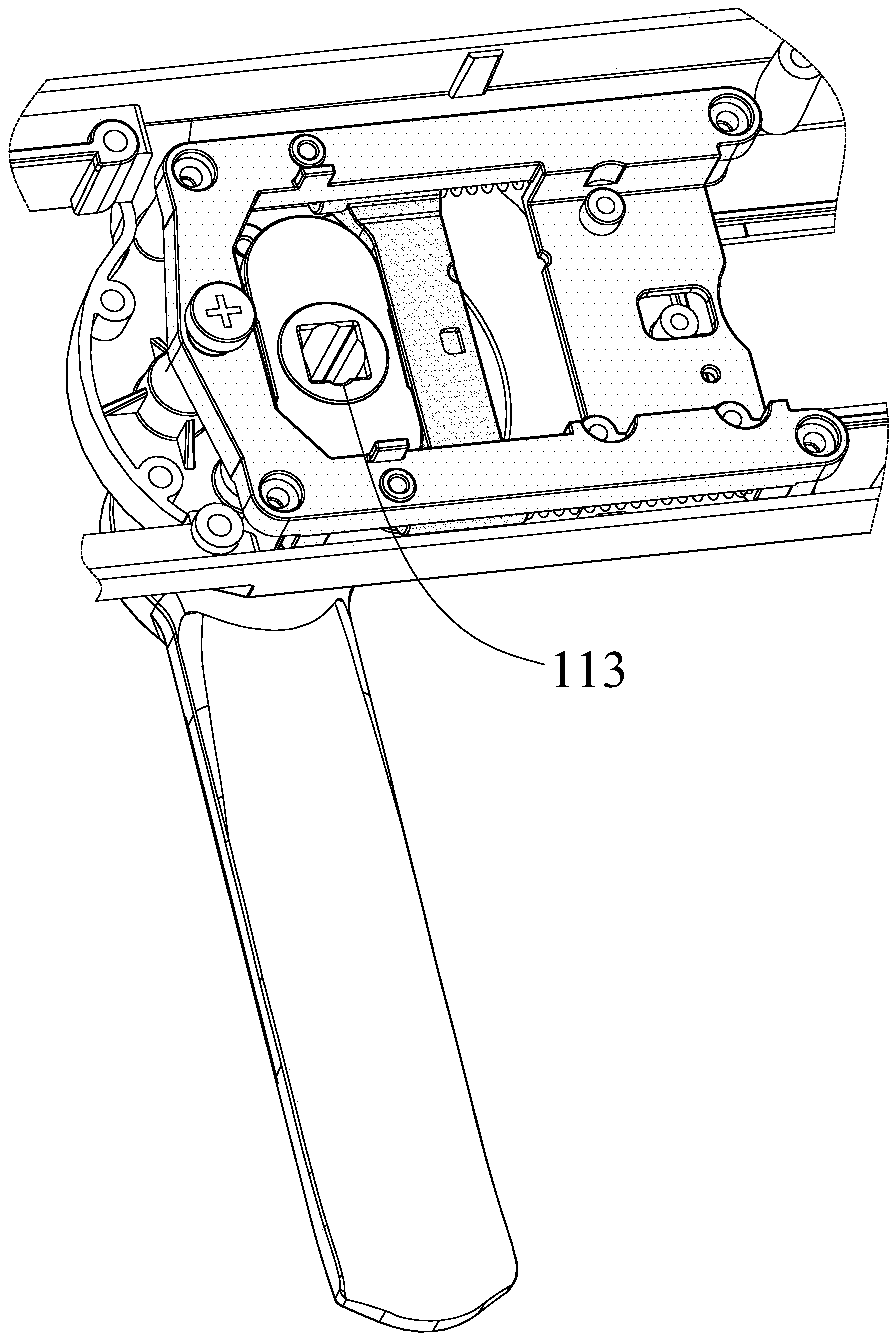
[0049] Also includes an external clutch assembly 10, which includes an outer rotating block 106 with a pin hole 111, a cover plate 101, a first rotating piece 104, a second rotating piece 104, and a latch 108; between the outer rotating block 106 and the cover plate 101 A clutch rotating block 102 is provided; the clutch rotating block 102 is provided with grooves for accommodating the first rotating piece 104 and the second rotating piece;
[0050] When the clutch rotating bloc...
PUM
 Abstract
Description
Claims
Application Information