Eureka AIR delivers breakthrough ideas for toughest innovation challenges, trusted by R&D personnel around the world.

DC stator excitation type mechanical-electro-liquid coupler

An excitation-type, electro-mechanical-hydraulic technology, applied in electromechanical devices, variable-capacity engines, machines/engines, etc., can solve problems such as large volume and mass, inability to output mechanical energy, and reduced reliability, achieving high transmission efficiency and increasing magnetic field. Strong, compact effect

Active Publication Date: 2018-01-16
QINGDAO UNIV
View PDF7 Cites 1 Cited by
  • Summary
  • Abstract
  • Description
  • Claims
  • Application Information

AI Technical Summary

Problems solved by technology

The former two adopt the method of connecting the motor and the liquid pump by the transmission shaft, which will bring many disadvantages: the noise and vibration caused by the non-concentricity of the coupling; the axial arrangement makes its volume and quality Larger; multiple connections and coordination reduce reliability and risk of leakage; efficiency is also very low; and only hydraulic energy can be output, mechanical energy and energy conversion cannot be output
[0003] In the prior art, it is common to use one or two tools for the conversion between different forms of main energy. In different working conditions, long-distance outdoor operations or purchasing spare tools, it is often necessary to purchase multiple types of tools. The cost of transportation and procurement has been greatly increased. For this reason, it is urgent to propose a mechanical structure design that can realize the conversion and flexible adjustment of various energies, and work stably and with low noise.

Method used


Image

  • DC stator excitation type mechanical-electro-liquid coupler
  • DC stator excitation type mechanical-electro-liquid coupler

Examples


Embodiment Construction

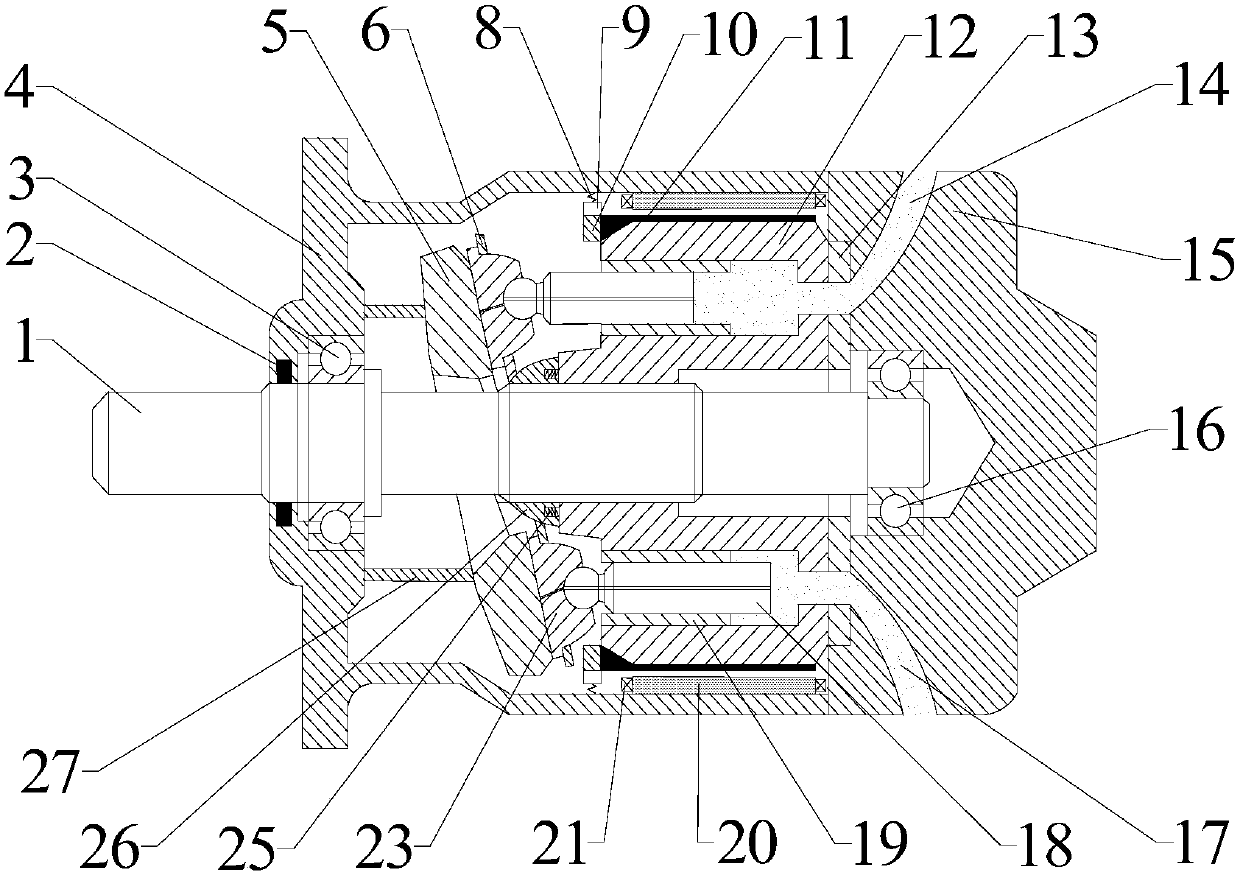
[0025] In order to understand the above-mentioned purpose, features and advantages of the present invention more clearly, the present invention will be further described below in conjunction with the accompanying drawings and embodiments. It should be noted that the positional relationship between left and right described in this embodiment is based on figure 1 What is shown prevails, and the embodiments of the present application and the features in the embodiments can be combined with each other under the condition of no conflict.

[0026] Many specific details are set forth in the following description to facilitate a full understanding of the present invention. However, the present invention can also be implemented in other ways than those described here. Therefore, the present invention is not limited to the specific embodiments disclosed below.

[0027] A DC stator excitation type electro-hydraulic coupler, the main structure includes a support system, a mechanical energ...


PUM


Abstract

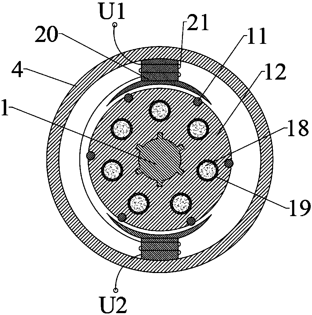
The invention discloses a DC stator excitation type mechanical-electro-liquid coupler which includes a supporting system, a mechanical energy conversion system, a hydraulic energy conversion system, and an electric energy conversion system. The supporting system includes a shell and a distribution plate. The hydraulic energy conversion system includes a cylinder body, a swash plate, a plunger andthe like. The electric energy conversion system includes a rotor coil, a stator iron core, an excitation winding, a lead terminal and the like. The stator iron core and the excitation winding are fixed in the shell, a transmission shaft and the cylinder body are connected by a spline and rotate synchronously, and the plunger reciprocates along the axis to absorb or output the hydraulic oil under the action of the swash plate. In specific work, the lead terminal is externally connected with the direct current, thereby achieving mutual conversion of mechanical energy, hydraulic energy and electric energy. The DC stator excitation type mechanical-electro-liquid coupler has the advantages of compact structure, high conversion efficiency and small pressure loss, achieves the coupling of mechanical-electro-liquid and the conversion of corresponding energy, and has broad application demands and industrialization prospect.

Description

technical field [0001] The invention relates to the technical field of energy conversion, in particular to a DC stator excitation electromechanical hydraulic coupler. Background technique [0002] There are three main hydraulic power sources, traditional motor-pump set, shielded motor pump and electro-hydraulic pump. The former two adopt the method of connecting the motor and the liquid pump by the transmission shaft, which will bring many disadvantages: the noise and vibration caused by the non-concentricity of the coupling; the axial arrangement makes its volume and quality Larger; multiple connections and coordination reduce reliability, and there is a risk of leakage; the efficiency is also very low; and only hydraulic energy can be output, mechanical energy and energy conversion cannot be output. [0003] In the prior art, it is common to use one or two tools for the conversion between different forms of main energy. In different working conditions, long-distance outdo...

Claims


Application Information

Patent Timeline
Patent Type & Authority Applications(China)
IPC IPC(8): F04B17/03F04B1/22F04B53/16H02K7/14F03C1/26F03C1/253H02K7/18
Inventor 张洪信赵清海侯典平华青松张铁柱
Owner QINGDAO UNIV
Why Eureka
Eureka Blog
Learn More