
Multi-component reflector for light module of a motor vehicle headlight

A technology of optical modules and headlights, which is applied in the field of optical modules, can solve the problems of increasing the cost of materials, and achieve the effects of reducing structural space, reducing tolerance chains, and low material input

Active Publication Date: 2018-01-16
AUTOMOTIVE LIGHTING REUTLINGEN GMBH
View PDF5 Cites 1 Cited by
  • Summary
  • Abstract
  • Description
  • Claims
  • Application Information

AI Technical Summary

Problems solved by technology

More cost due to increased material usage

Method used


Image

  • Multi-component reflector for light module of a motor vehicle headlight
  • Multi-component reflector for light module of a motor vehicle headlight
  • Multi-component reflector for light module of a motor vehicle headlight

Examples


Embodiment Construction

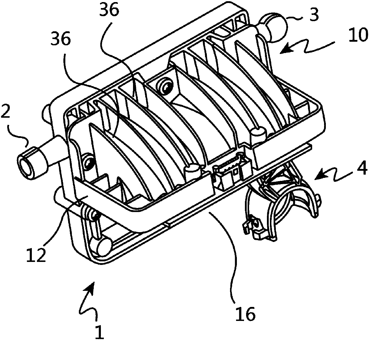
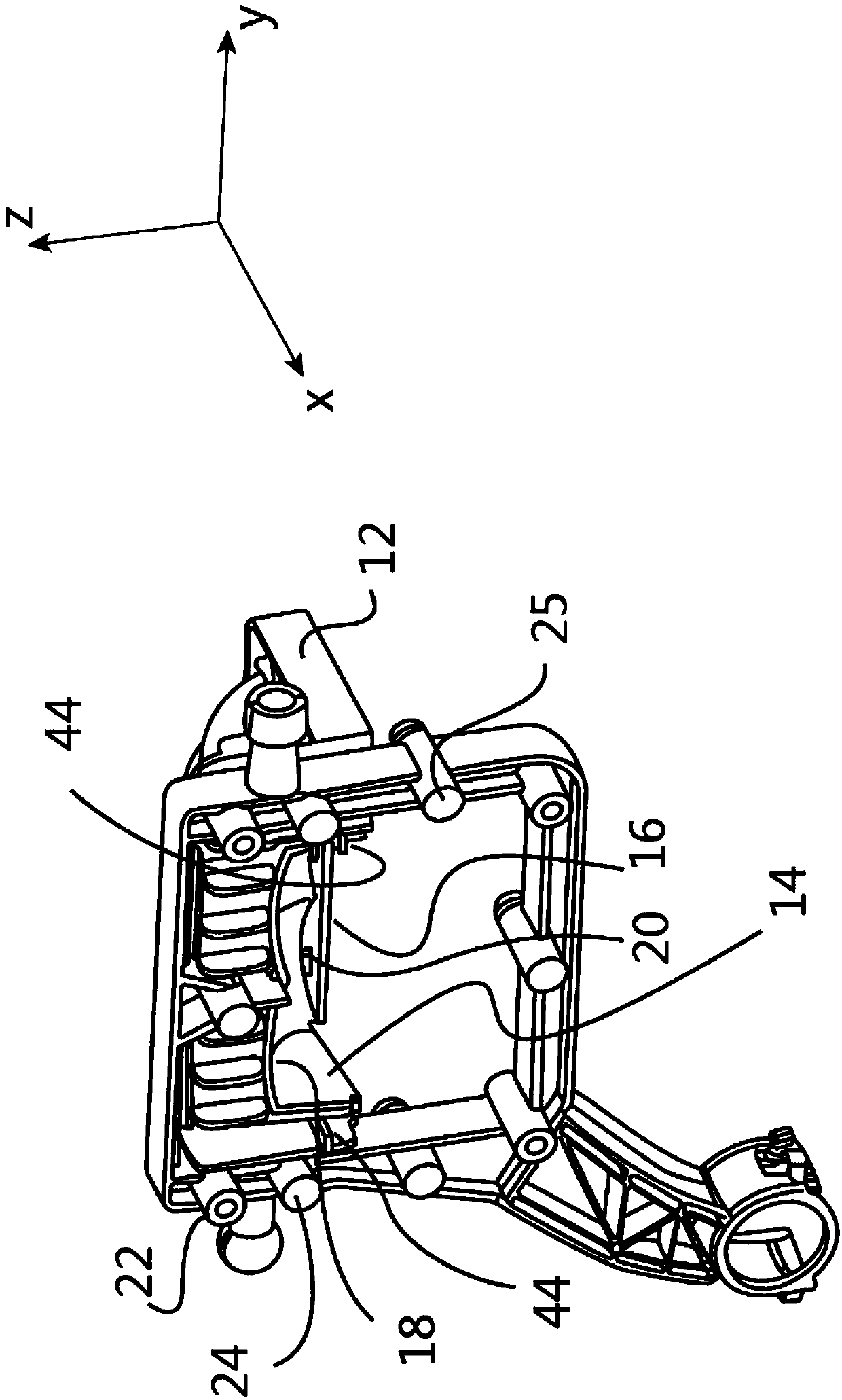
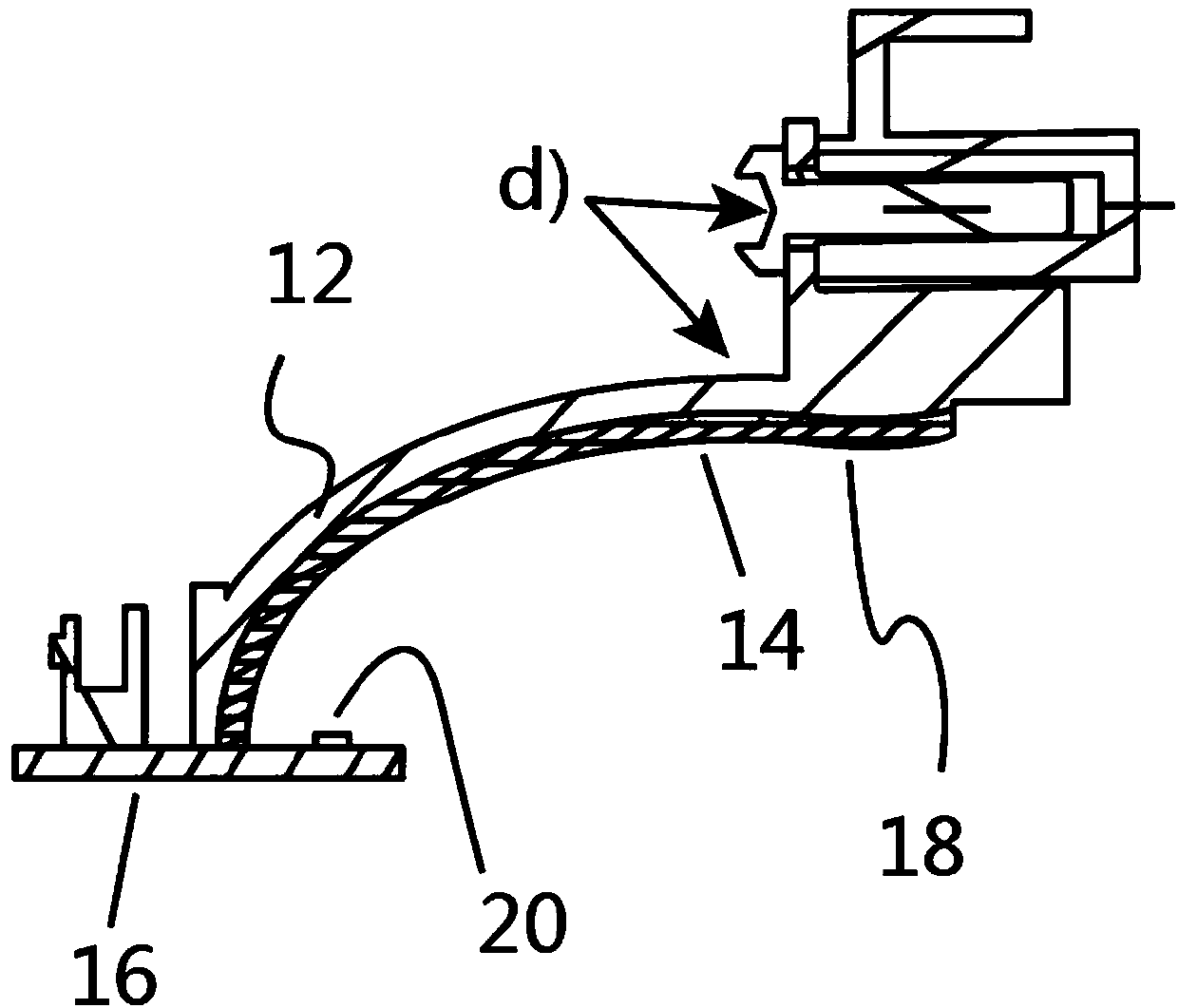
[0031] figure 1 and figure 2 A pivot frame 1 of a motor vehicle headlight, which is a component of an exemplary embodiment of a light module 10 according to the invention, is shown in detail. For this, figure 1 shows a perspective view of the rear side of the swing frame 1 and the light module 10, while figure 2 A perspective view of the front side of the swing frame 1 and the light module 10 is shown.

[0032] In the exemplary embodiment shown, the pivot frame 1 has a cylindrical bearing pin 2 , a spherical bearing pin 3 and a receptacle 4 for the spherical bearing pin. The bearing pins 2 , 3 and the receptacles form an articulated structure by means of which the pivot frame is mounted pivotably in the housing of the motor vehicle headlight during its conventional use in the motor vehicle headlight. The cylindrical bearing pin 2 together with the spherical bearing pin 3 defines a pivot axis for the lighting width adjustment, and the spherical bearing pin 38 together wit...


PUM


Abstract

The invention relates to a light module of a motor vehicle headlight. The light module has a reflector, a cooling body and a circuit board with a semiconductor light source, wherein the reflector hasa supporting housing made of a first material and a reflecting housing made of a second material and abutting against the supporting housing, the reflecting housing and the circuit board have positioning structures which are complementary and jointed to each other, and the supporting housing is thermally coupled to the circuit board through appropriate connection.

Description

technical field [0001] The invention relates to a light module of a motor vehicle headlight, which has a reflector, a heat sink and a printed circuit board with semiconductor light sources. Such light modules are known per se. Background technique [0002] Today, reflectors are usually made of plastics (eg thermosetting plastics, thermoplastics) or of metallic materials (eg aluminium). These materials are often surface treated to meet optical requirements. [0003] The surface accuracy to be achieved is particularly dependent on the type of surface treatment, which must be taken into account when designing the optical module. Expensive manufacturing tools, such as painting equipment, are today required to prepare reflector blanks for final surface treatment. For this a process window must be set and the maintenance of the process window must be monitored in order to detect and limit quality fluctuations. Depending on the material used, there are restrictions on the shape...

Claims


Application Information

Patent Timeline
Patent Type & Authority Applications(China)
IPC IPC(8): F21S41/30F21V7/10F21W107/10F21W102/00
CPCF21S41/19F21S41/192F21S41/39F21S41/37F21S41/148F21S41/16F21S45/47F21S45/48
Inventor A·迈尔S·布劳恩C·奥托E-O·罗森汉R·洛伊特M·比德尔曼E·辛格
Owner AUTOMOTIVE LIGHTING REUTLINGEN GMBH
Learn More