Component multiple size measuring method and system based on binocular vision

A binocular vision and multi-size technology, applied in the field of visual measurement, can solve problems such as difficulty in feature point matching

Inactive Publication Date: 2018-01-16
WUHAN UNIV OF SCI & TECH
View PDF5 Cites 28 Cited by
  • Summary
  • Abstract
  • Description
  • Claims
  • Application Information

AI Technical Summary

Problems solved by technology

[0005] The embodiment of the present invention provides a binocular vision-based multi-dimensional measurement method and system for p

Method used


Image

  • Component multiple size measuring method and system based on binocular vision
  • Component multiple size measuring method and system based on binocular vision
  • Component multiple size measuring method and system based on binocular vision

Examples


Embodiment 1

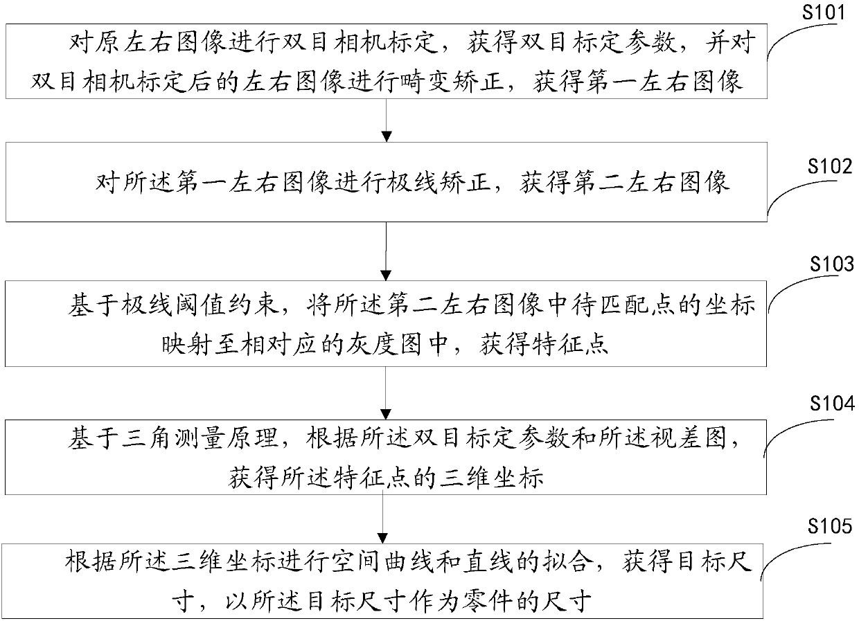
[0068] This embodiment provides a method for measuring multiple dimensions of parts based on binocular vision, please refer to figure 1 , the method includes:

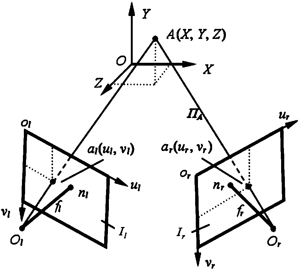
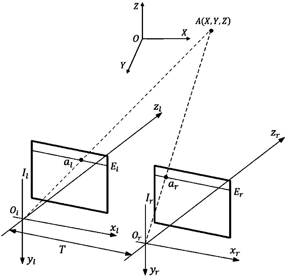
[0069] Step S101: Carry out binocular camera calibration on the original left and right images to obtain binocular calibration parameters, the binocular calibration parameters include the focal length, principal point coordinates, horizontal displacement and distortion coefficient of the left and right cameras, and the left and right images after binocular camera calibration Perform distortion correction on the image to obtain the first left and right images;

[0070] Step S102: Perform epipolar correction on the first left and right images to obtain second left and right images;

[0071] Step S103: Based on the epipolar threshold constraint, map the coordinates of the points to be matched in the second left and right images to the corresponding grayscale images to obtain feature points, wherein the feature points inc...

Embodiment 2

[0110] Based on the same inventive concept as that of Embodiment 1, Embodiment 2 of the present invention provides a multi-dimensional measurement system for parts based on binocular vision. Please refer to Figure 4 , the system includes:

[0111] The distortion correction module 201 is used to perform binocular camera calibration on the original left and right images, and obtain binocular calibration parameters. The binocular calibration parameters include the focal length, principal point coordinates, horizontal displacement, and distortion coefficient of the left and right cameras. Distortion correction is performed on the calibrated left and right images to obtain the first left and right images;

[0112] An epipolar line correction module 202, configured to perform epipolar line correction on the first left and right images to obtain second left and right images;

[0113] The feature matching module 203 is configured to map the coordinates of the points to be matched in...

Embodiment 3

[0129] Based on the same inventive concept as that of Embodiment 1, Embodiment 3 of the present invention provides a computer-readable storage medium 500. Please refer to Figure 5 , a computer program 511 is stored thereon, and when the program is executed by the processor, the following steps are implemented:

[0130] Carry out binocular camera calibration on the original left and right images to obtain binocular calibration parameters, which include the focal length, principal point coordinates, horizontal displacement and distortion coefficient of the left and right cameras, and distort the left and right images after binocular camera calibration Correction, to obtain the first left and right images;

[0131] performing epipolar correction on the first left and right images to obtain second left and right images;

[0132] Based on the epipolar threshold constraint, the coordinates of the points to be matched in the second left and right images are mapped to corresponding ...


PUM


Abstract

The invention discloses a component multiple size measuring method and system based on binocular vision. The component multiple size measuring method based on binocular vision includes the steps: performing binocular camera calibration on original left and right images to obtain the binocular calibration parameters, and performing distortion correction on the left and right images after binocularcamera calibration to obtain first left and right images; performing polar correction on the first left and right images to obtain second left and right views; based on polar threshold constraints, mapping the points to be matched in the second left and right images to the corresponding grey-scale map to obtain characteristic points; based on a triangulation principle, according to the binocular calibration parameters and a parallax map, obtaining the three dimensional coordinates of the characteristic points; and according to the three dimensional coordinates, performing space curve and linefitting to obtain the target size, and taking the target size as the size of the component. The component multiple size measuring method and system based on binocular vision can solve the technical problem that a current binocular vision measuring method is difficult to match characteristic points.

Description

technical field [0001] The invention relates to the technical field of visual measurement, in particular to a binocular vision-based multi-dimensional measurement method and system for parts. Background technique [0002] With the advent of the industry 4.0 era, the concept of intelligent manufacturing and intelligent factory has gradually entered people's field of vision, and people have higher and higher requirements for the degree of automatic production of products. Sample detection, measurement and other applications. The common feature of this type of processing and production is continuous mass production, which requires a very high degree of automation. With the improvement and improvement of industrial manufacturing technology and processing technology, higher requirements are put forward for detection methods, detection speed and accuracy. Traditional manual detection methods, such as vernier calipers, micrometers and three-coordinate measuring instruments, have ...

Claims


Application Information

Patent Timeline
IPC IPC(8): G01B11/00
Inventor 张俊勇伍世虔徐历洪
Owner WUHAN UNIV OF SCI & TECH
Why Eureka
Try Eureka