Asynchronous motor rotor broken bar fault determination method

A technology for asynchronous motors and rotor broken bars, which is applied in the direction of motor generator testing, etc., can solve the problems of misjudgment and missed judgment, misjudgment, current detection method is easily affected by load, etc.

Inactive Publication Date: 2018-01-16
马鞍山马钢华阳设备诊断工程有限公司
View PDF6 Cites 10 Cited by
  • Summary
  • Abstract
  • Description
  • Claims
  • Application Information

AI Technical Summary

Problems solved by technology

[0003] At present, the method for judging the broken rotor bar of an asynchronous motor is mainly based on detecting the current of the motor, and the analysis method of the motor current signal has its own defects: this method is affected by the load level and operating frequency
Its shortcomings are: the current detection method is easily affected by the load, the accuracy is low, and there are misjudgments and missed judgments
Its shortcoming is that the invention still relies on the stator current signal to judge the fault of the broken rotor bar. Once the stator current is affected by the load fluctuation, there is still the possibility of misjudgment through the control strategy of the stator voltage and current coupling.

Method used


Image

  • Asynchronous motor rotor broken bar fault determination method
  • Asynchronous motor rotor broken bar fault determination method
  • Asynchronous motor rotor broken bar fault determination method

Examples


Embodiment 1

[0096] A method for judging a broken bar fault of an asynchronous motor rotor, the steps of which are:

[0097] A. Construct a fault detection system for rotor broken bar of asynchronous motor;

[0098] B. Connect the Ia, Ib, and Ic current clamps to the A, B, and C phase cables one by one, pay attention to the connection direction of the current clamps, and make the direction of the arrow on the current clamps point to the direction of the motor;

[0099] C. Put the voltage clips of Va, Vb, and Vc on the terminals of A, B, and C phases in one-to-one correspondence;

[0100] D. The phase sequence of the detection current, if the display sequence is Ia, Ib, Ic and the phase angle is 120 degrees, the connection is correct.

[0101] E. The phase sequence of the detection voltage, if the displayed sequence is Vab, Vbc, Vca and the phase angle is 120 degrees, the connection is correct;

[0102] F. Detect the phase lag angle so that the three-phase lag angle matches, indicating th...

Embodiment 2

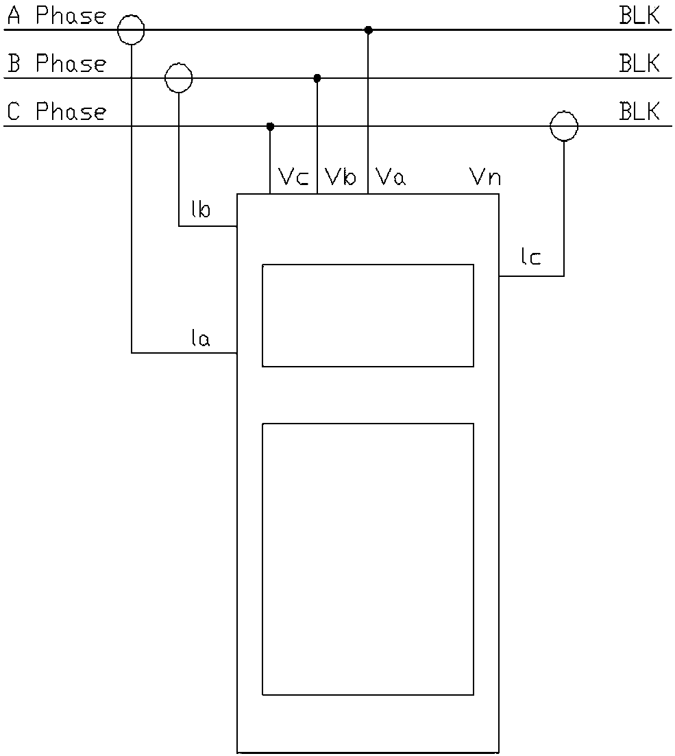
[0106] Such as figure 2 As shown, the asynchronous motor rotor broken bar fault detection system of this embodiment includes a power analyzer and a collector, and the current clamps of the power analyzer are respectively connected to the A, B and C phase cables one by one. The voltage clamps are respectively clamped on the A, B, and C phase terminals in one-to-one correspondence; the power analyzer is connected to the collector.

Embodiment 3

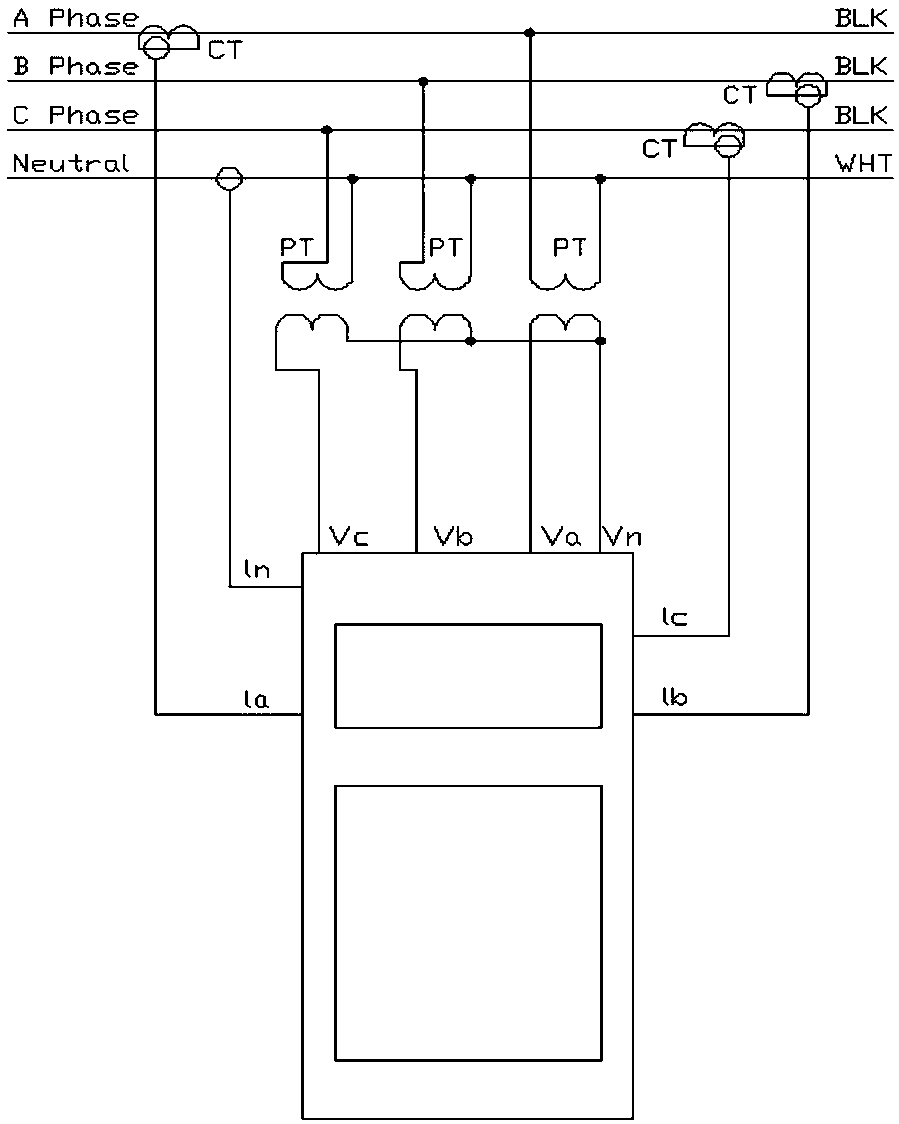
[0108] Such as figure 1 As shown, when the motor is a high-voltage motor, a broken rotor bar fault detection system of an asynchronous motor in this embodiment includes a voltage transformer and a current transformer, and the current transformer passes through the A, B, and C phase cables. The output end is connected to the power analyzer, the primary end of the voltage transformer is connected to the A, B, and C phase terminals, the secondary end of the voltage transformer is connected to the power analyzer, and the power analyzer is connected to the collector. The multiplier setting of the voltage and current of the acquisition instrument corresponds to the transformation ratio of the voltage transformer and the current transformer respectively.


PUM


Abstract

The invention discloses an asynchronous motor rotor broken bar fault determination method, and belongs to the motor fault determination field. The asynchronous motor rotor broken bar fault determination method includes the steps: an acquisition instrument acquires the voltage and current data through a current clamp and a voltage clamp, and performs spectrum analysis on current; if the current signal is normal, a motor rotor has no broken bar faults, and if the current signal is abnormal, one sideband appears at each of the positions that the power frequency differs from the slip frequency bytwo times, and then the text step is performed; and spectrum analysis is performed on voltage, and if the voltage signal is normal, the motor rotor has no broken bar faults, and if the voltage signalis abnormal and when one sideband appears at each of the positions that the power frequency differs from the slip frequency by two times, a broken bar fault exists in the motor rotor. For solving theproblem that the motor current signal analysis method in the rotor broken bar fault of an asynchronous motor in the prior art may encounter error determination, the asynchronous motor rotor broken barfault determination method uses the mode of using the stator current and the stator voltage to determine successively to detect the rotor broken bar fault, thus reducing the error determination rate.

Description

technical field [0001] The invention relates to the field of motor fault judgment, in particular to a method for judging a broken bar fault of an asynchronous motor rotor. Background technique [0002] With the advancement of modern science and technology and the increasing scale of power systems, motors play an increasingly important role in modern industrial production. Motor failure will not only damage the motor itself, but also affect the normal operation of the entire system, and even endanger personal safety in serious cases, causing huge economic losses and significant social impacts. Therefore, the diagnosis of motor faults has important significance and engineering practical value. Studying the monitoring and fault diagnosis technology of high-voltage asynchronous motors is of great significance to prevent the occurrence of high-voltage asynchronous motor faults, find and eliminate faults in time, ensure the reliable operation of induction motors, and improve produ...

Claims


Application Information

Patent Timeline
Patent Type & Authority Applications(China)
IPC IPC(8): G01R31/34
Inventor 贾维龙王顺利张继海刘健王岿
Owner 马鞍山马钢华阳设备诊断工程有限公司
Why Eureka
Try Eureka