Asynchronous motor rotor broken bar fault judgment method with electric signals and vibration signals integrated
An asynchronous motor and vibration signal technology, which is used in motor generator testing, mechanical component testing, and machine/structural component testing.
- Summary
- Abstract
- Description
- Claims
- Application Information
AI Technical Summary
Problems solved by technology
Method used
Image
Examples
Embodiment 1
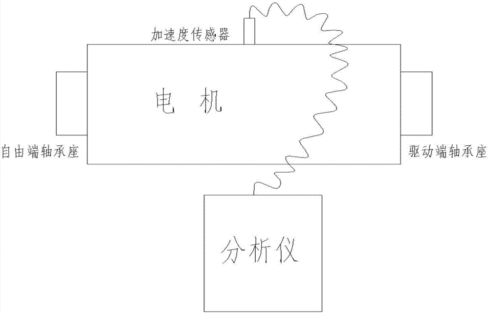
[0116] A method for judging a broken bar fault of an asynchronous motor rotor integrated with electrical signals and vibration signals, the steps of which are as follows:
[0117] A. Construct a fault detection system for rotor broken bar of asynchronous motor;
[0118] B. Connect the Ia, Ib, and Ic current clamps to the A, B, and C phase cables one by one, pay attention to the connection direction of the current clamps, and make the direction of the arrow on the current clamps point to the direction of the motor;
[0119] C. Put the voltage clips of Va, Vb, and Vc on the terminals of A, B, and C phases in one-to-one correspondence;
[0120] D. The phase sequence of the detection current, if the display sequence is Ia, Ib, Ic and the phase angle is 120 degrees, the connection is correct.
[0121] E. The phase sequence of the detection voltage, if the displayed sequence is Vab, Vbc, Vca and the phase angle is 120 degrees, the connection is correct;
[0122] F. Detect the phas...
Embodiment 2
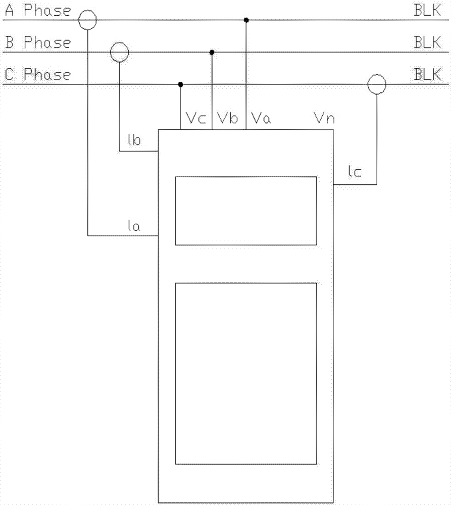
[0130] like figure 2 As shown, the asynchronous motor rotor broken bar fault detection system of this embodiment includes a power analyzer and a collector, and the current clamps of the power analyzer are respectively connected to the A, B, and C phase cables one by one. The voltage clamps are respectively clamped on the A, B, and C phase terminals in one-to-one correspondence; the power analyzer is connected to the collector.
Embodiment 3
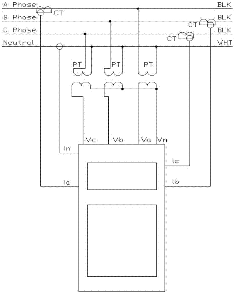
[0132] like figure 1 As shown, when the motor is a high-voltage motor, a broken rotor bar fault detection system of an asynchronous motor in this embodiment includes a voltage transformer and a current transformer, and the current transformer passes through the A, B, and C phase cables. The output terminal is connected to the power analyzer, the primary terminal of the voltage transformer is connected to the terminals of A, B, and C phases, the secondary terminal of the voltage transformer is connected to the power analyzer, and the power analyzer is connected to the collector. The multiplier setting of the voltage and current of the acquisition instrument corresponds to the transformation ratio of the voltage transformer and the current transformer respectively.
PUM
 Abstract
Description
Claims
Application Information
 - R&D
- Intellectual Property
- Life Sciences
- Materials
- Tech Scout
- Unparalleled Data Quality
- Higher Quality Content
- 60% Fewer Hallucinations
Browse by: Latest US Patents, China's latest patents, Technical Efficacy Thesaurus, Application Domain, Technology Topic, Popular Technical Reports.
© 2025 PatSnap. All rights reserved.Legal|Privacy policy|Modern Slavery Act Transparency Statement|Sitemap|About US| Contact US: help@patsnap.com


