
Integrated light attenuation device

An optical attenuation and integrated technology, applied in the coupling of optical waveguides, etc., can solve the problems of unfavorable development trends, high cost of adjustable optical attenuators, and large overall space volume, so as to simplify external connections and improve overall performance requirements , the effect of reducing production costs

Pending Publication Date: 2018-01-16
O NET COMM (SHENZHEN) LTD
View PDF0 Cites 3 Cited by
  • Summary
  • Abstract
  • Description
  • Claims
  • Application Information

AI Technical Summary

Problems solved by technology

[0007] The technical problem to be solved by the present invention is to provide an integrated optical attenuation device for the above-mentioned defects of the prior art, which solves the problem that the existing adjustable optical attenuator has a large cost and a large overall space volume, which is not conducive to low cost and miniaturization The question of the development trend of integration

Method used


Image

  • Integrated light attenuation device
  • Integrated light attenuation device
  • Integrated light attenuation device

Examples


Embodiment Construction

[0026] Now in conjunction with the accompanying drawings, the preferred embodiments of the present invention will be described in detail.

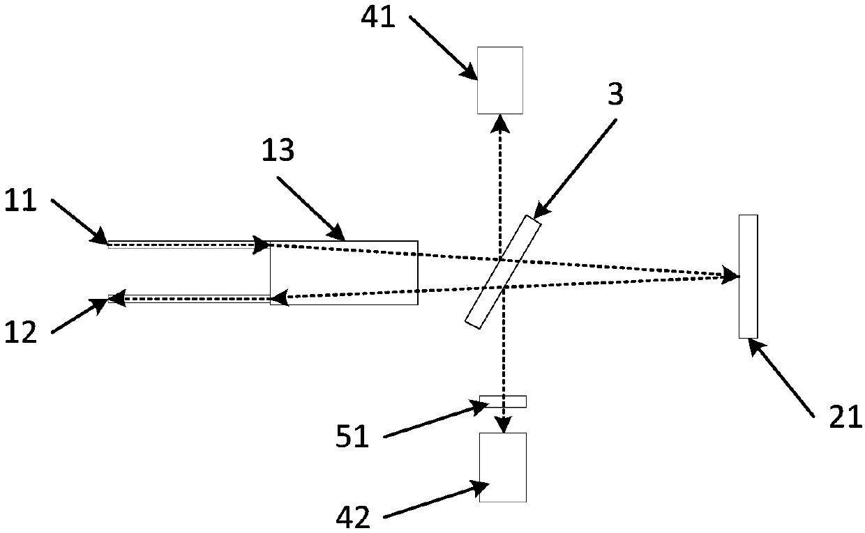
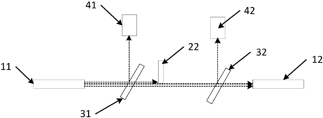
[0027] Such as figure 1 and figure 2 As shown, the present invention provides a preferred embodiment of an integrated optical attenuation device.

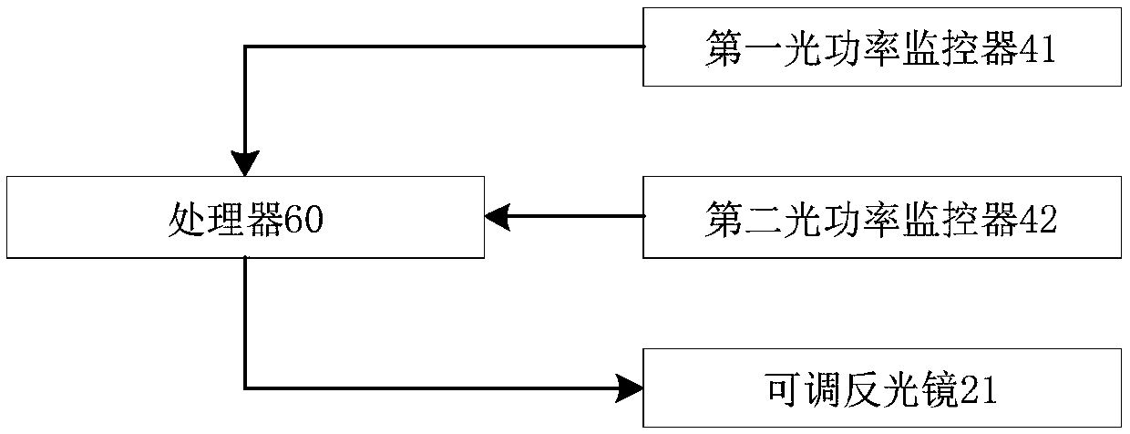
[0028] An integrated optical attenuation device. The optical attenuation device includes an input optical fiber 11, an output optical fiber 12 and an optical attenuation mechanism. After the optical signal emitted by the input optical fiber 11 is attenuated by the optical attenuation mechanism, it is incident on the output optical fiber 12. The optical attenuation device also includes a first optical splitter arranged between the input optical fiber 11 and the optical attenuation mechanism, and a second optical splitter arranged between the optical attenuation mechanism and the output optical fiber 12, and the optical attenuation device also includes a first An optical power monitor 41 and a...


PUM


Abstract

The invention relates to the light attenuation device and particularly relates to an integrated light attenuation device. The integrated light attenuation device comprises a first light splitter, a second light splitter, a first optical power monitoring device and a second optical power monitoring device. An optical signal emitted by an input optical fiber goes through a first light splitter. Partof optical signals are reflected to the first optical power monitoring device through the first light splitter . An optical signal emitted by an optical attenuation mechanism goes through the secondlight splitter. Part of optical signals which go into an output optical fiber are reflected into the second optical power monitor through the second light splitter. The invention designs an integratedlight attenuation device in which optical power monitoring devices are arranged. The integrated light attenuation device does not need to adopt extra optical power monitoring devices, reduces the volume occupying spaces, simplifies external wire connection, makes product integrated, improves stability, reduces production cost and improves integral performance.

Description

technical field [0001] The invention relates to the field of optical attenuators, in particular to an integrated optical attenuation device. Background technique [0002] The optical attenuator is a device used to attenuate the optical power. It is mainly used in the index measurement of the optical fiber system, the signal attenuation of the short-distance communication system and the system test and other occasions. [0003] Optical attenuator is a very important fiber optic passive device. It can attenuate the optical signal energy according to the user's requirements. It is often used to absorb or reflect the optical power margin, evaluate the loss of the system and various tests. . At present, serialized optical attenuators have been widely used in the field of optical communication, bringing convenience to users. [0004] Generally speaking, optical attenuators can be divided into fixed attenuators, graded adjustable attenuators, continuously adjustable attenuators, ...

Claims


Application Information

Patent Timeline
IPC IPC(8): G02B6/26
Inventor 谢红夏小斌
Owner O NET COMM (SHENZHEN) LTD
Learn More