
Job dependence relation representation method, job display and scheduling control methods, and apparatuses

A dependency relationship and job scheduling technology, applied in data processing applications, resources, office automation, etc., can solve problems such as inconvenient operation and maintenance management, cumbersome work, and information loss, and achieve convenient monitoring and maintenance, low technical cost, and design efficiency high effect

Active Publication Date: 2018-01-16
CHINA CONSTRUCTION BANK
View PDF3 Cites 7 Cited by
  • Summary
  • Abstract
  • Description
  • Claims
  • Application Information

AI Technical Summary

Problems solved by technology

[0008] 1. The design and archiving of dependency diagrams require the use of professional software or scheduling products, which have high requirements for technical capabilities and software environments, and increase production costs
[0009] 2. During job deployment, it is necessary to convert the dependency diagram into a dependent configuration item. On the one hand, the relationship diagram produced in the design phase is separated from the code of the dependent configuration item, and the version management is easy to be confused; on the other hand, when the dependency relationship needs to be adjusted, It is necessary to modify the design and re-convert the configuration items, which is cumbersome and inefficient
[0010] 3. The existing conversion from dependency diagram to table or file with specific structure is the conversion from visual graphics to code file, and there is information loss
In addition, it is necessary to monitor the job flow status and intervene in abnormal jobs during scheduling management. It is difficult to visually observe the positional relationship and before and after effects of jobs in the overall process only from dependent configuration items. It is difficult to analyze the progress of job flow execution, and operation and maintenance management is inconvenient.

Method used


Image

  • Job dependence relation representation method, job display and scheduling control methods, and apparatuses
  • Job dependence relation representation method, job display and scheduling control methods, and apparatuses
  • Job dependence relation representation method, job display and scheduling control methods, and apparatuses

Examples


Embodiment Construction

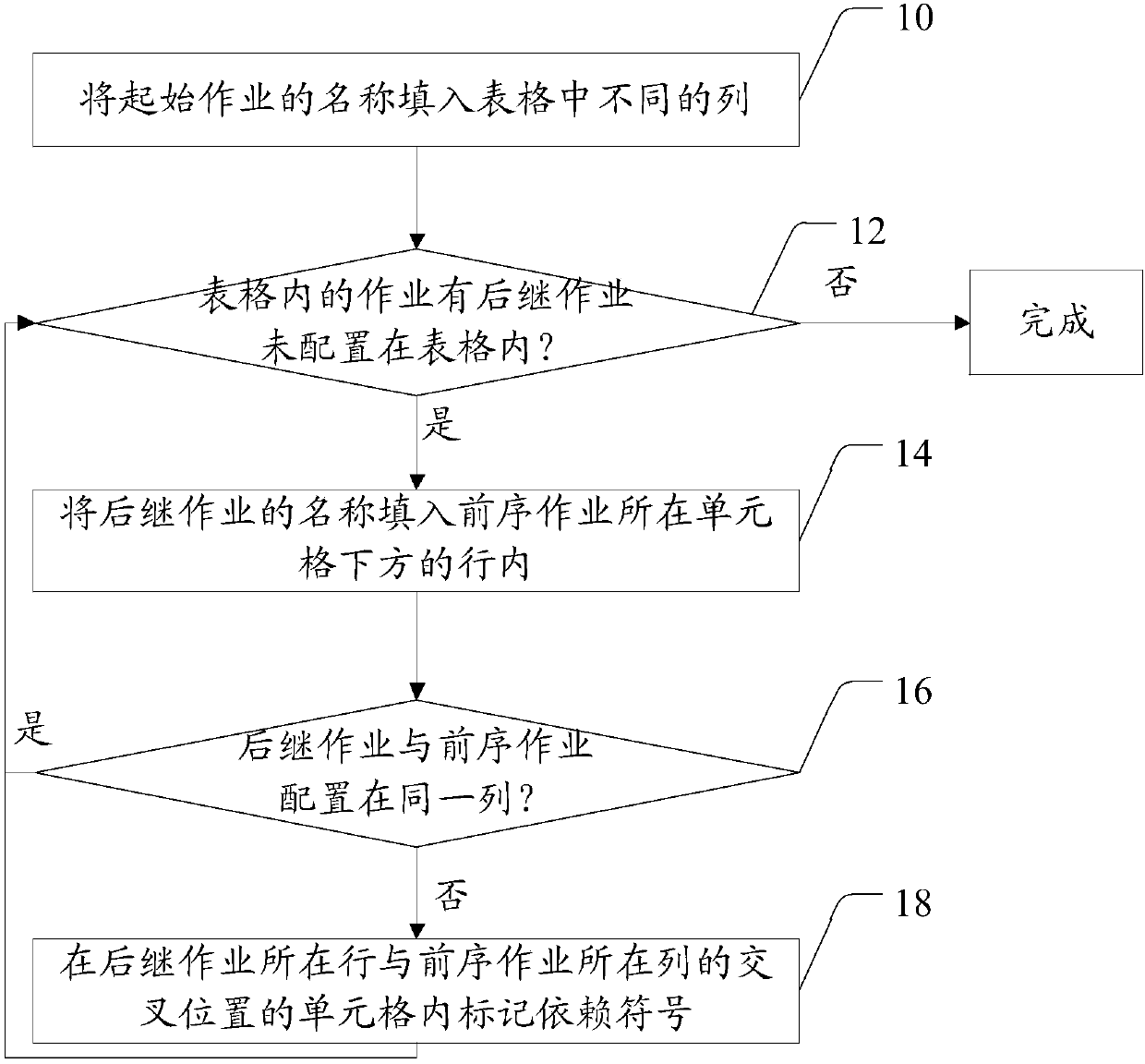
[0055] Various aspects of the present invention will be described in detail below with reference to the drawings and specific embodiments. Wherein, well-known modules, units and their mutual connections, links, communications or operations are not shown or described in detail. Also, the described features, architectures, or functions may be combined in any manner in one or more implementations. It should be understood by those skilled in the art that the various implementations described below are only for illustration, rather than limiting the protection scope of the present invention. It can also be easily understood that the modules or units or steps in the embodiments described herein and shown in the drawings can be combined and designed in various configurations.

[0056] First of all, the names involved or possibly involved in the present invention are explained as follows:

[0057] Jobs, job streams:

[0058] A process, process or project is often divided into sever...


PUM


Abstract

The invention discloses a job dependence relation representation method, job display and scheduling control methods, and apparatuses. The job dependence relation representation method includes: configuring a job dependence relation in a table according to a job dependence relation and a job configuration policy, and obtaining a job dependence relation table used for representing the job dependencerelation, wherein the table comprises cells used for configuring job names and dependence relations. The job scheduling control method comprises: determining and executing a subsequent job accordingto a job state and the above job dependence relation table. By employing the methods and the apparatuses, the position relation and the contextual influence of the job in the whole process can be visually observed, and the execution progress of job streams can be easily analyzed; and after configuration of the dependence relation table, the update of the job scheduling sequence can be accomplishedwithout conversion processing, and the deployment efficiency is improved.

Description

technical field [0001] The present invention relates to the fields of data processing and job scheduling, and more specifically, to a job dependency representation method, job display and scheduling control method and device. Background technique [0002] In the job flow, set dependencies between two jobs to ensure the causal logic of the business. Therefore, some jobs must be started after other related jobs are completed, that is, the start of a job is based on the completion of all its predecessor jobs as a prerequisite; other jobs have no prerequisites and can be scheduled to start at any time . [0003] In the existing technology, from job flow design to deployment, and even job scheduling and execution, the processing methods related to dependencies are generally: [0004] In the design phase: generate dependency diagrams according to business logic relationships and edit archives; [0005] In the deployment phase: parse the dependency graph into a table or file of ...

Claims


Application Information

Patent Timeline
Patent Type & Authority Applications(China)
IPC IPC(8): G06Q10/06G06Q10/10
Inventor 张扬
Owner CHINA CONSTRUCTION BANK
Learn More