
Clamping plate type fixer for orthopedics department

A splint-type, fixer technology, applied in fractures, medical science, bathing devices, etc., can solve problems such as unfavorable bone recovery of patients, inability to adapt to patients of different sizes, and inconvenient operation for medical staff, so as to avoid long-term blood gas circulation. , Accelerate the recovery effect of treatment, good auxiliary therapeutic effect

Inactive Publication Date: 2018-01-19
陈雷
View PDF4 Cites 5 Cited by
  • Summary
  • Abstract
  • Description
  • Claims
  • Application Information

AI Technical Summary

Problems solved by technology

[0003] With the development of material science, some complex fractures can gradually be treated with internal fixation. At present, the clinically used orthopedic splint is generally composed of a wooden board. When fixing a fracture for a patient, multiple people are required to help fix it with bandages. , the operation is very troublesome, time-consuming and labor-intensive, which brings great inconvenience to the medical staff. During the fixation process, the fixation displacement is usually caused, and the affected part is not really fixed, resulting in slow recovery. Moreover, the existing orthopedic fixation devices are generally Fixed space size, poor adjustability, unable to adapt to patients with different body types, or patients with different recovery periods, the fastening effect is poor, which is not conducive to bone recovery of patients

Method used


Image

  • Clamping plate type fixer for orthopedics department
  • Clamping plate type fixer for orthopedics department

Examples


Embodiment Construction

[0017] In order to make the purpose, technical solutions and advantages of the embodiments of the present invention clearer, the technical solutions in the embodiments of the present invention will be clearly and completely described below in conjunction with the embodiments of the present invention. Based on the embodiments of the present invention, all other embodiments obtained by persons of ordinary skill in the art without creative efforts fall within the protection scope of the present invention.

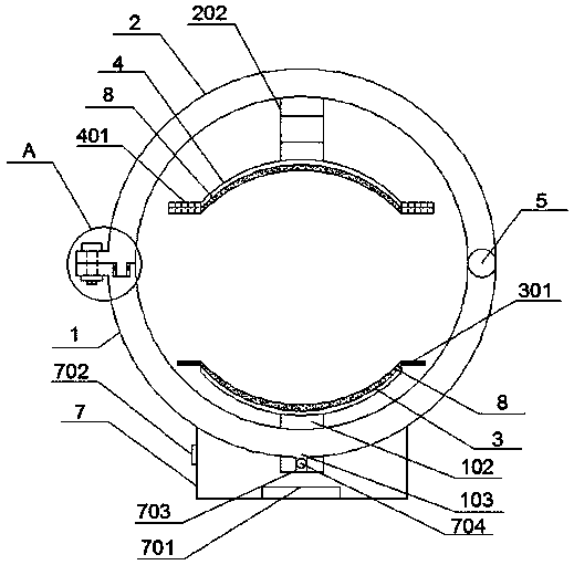
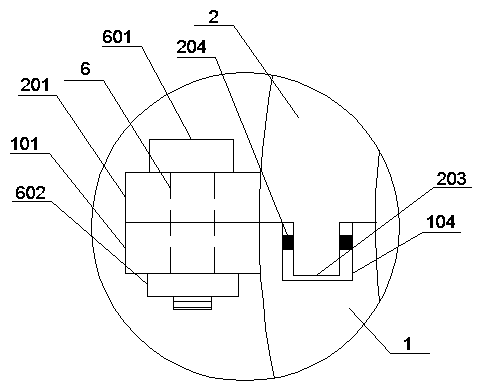
[0018] An orthopedic splint fixator, such as figure 1 , 2 As shown, it includes an outer splint one, an outer splint two, an inner splint one, and an inner splint two. One end of the outer splint one and the outer splint two is hinged by a rotating shaft, and the other end is respectively provided with a positioning plate one and a positioning plate two. Positioning plate 1 and positioning plate 2 are correspondingly provided with threaded positioning holes, the inner side of...


PUM


Abstract

The invention provides a clamping plate type fixer for the orthopedics department. The clamping plate type fixer comprises a first outer clamping plate, a second outer clamping plate, a first inner clamping plate and a second inner clamping plate. One end of the first outer clamping plate and one end of the second outer clamping plate are hinged through a rotating shaft, and the other end of the first outer clamping plate and the other end of the second outer clamping plate are provided with a first positioning plate and a second positioning plate respectively. Threaded positioning holes are correspondingly formed in the first positioning plate and the second positioning plate in a penetrating mode. The inner side of the first outer clamping plate is connected with the first inner clampingplate through a fixing rod. The two sides of the first inner clamping plate are provided with bearing strip plates. The inner side of the second outer clamping plate is connected with the second inner clamping plate through a telescopic sleeve rod. The two sides of the second inner clamping plate are provided with balance weight strip plates which correspond to the bearing strip plates. The clamping plates are large in clamping space and size and strong in adaptability, and the clamping plate type fixer has self-adjusting property, saves time and labor, is good in clamping effect and has a good auxiliary treatment property and a treatment restoration acceleration effect.

Description

technical field [0001] The invention relates to the technical field of medical instruments, in particular to an orthopedic splint type fixator. Background technique [0002] Orthopedics, also known as orthopedic surgery, is a specialty or discipline of medicine, specializing in the study of the anatomy, physiology and pathology of the musculoskeletal system, using drugs, surgery and physical methods to maintain and develop the normal form and function of this system, and treating this system. A systemic injury. [0003] With the development of material science, some complex fractures can gradually be treated with internal fixation. At present, the clinically used orthopedic splint is generally composed of a wooden board. When fixing a fracture for a patient, multiple people are required to help fix it with bandages. , the operation is very troublesome, time-consuming and labor-intensive, which brings great inconvenience to the medical staff. During the fixation process, the...

Claims


Application Information

Patent Timeline
Patent Type & Authority Applications(China)
IPC IPC(8): A61F5/058A61H33/06A61N2/08
Inventor 陈雷
Owner 陈雷
Learn More