
Orthopedic tool position and trajectory GUI

a technology of trajectory and orthopedic tool, applied in the field of medical and surgical procedures, can solve the problems of large and expensive equipment, inability to predict the longevity of the prosthesis, and inability to achieve the effect of functional efficacy,

Inactive Publication Date: 2014-05-15
ORTHOSENSOR
View PDF10 Cites 48 Cited by
  • Summary
  • Abstract
  • Description
  • Claims
  • Application Information

AI Technical Summary

Benefits of technology

The invention relates to a system for guiding medical devices to precise locations on or within a patient's body during surgery or other medical procedures. The system uses motion and orientation sensing technology to track the location and orientation of the medical device or prosthetic components in real-time and can help improve the accuracy and predictability of outcomes. The system can also help reduce the need for expensive and bulky equipment and can be used in procedures performed by physicians and surgeons of varying levels of skill. The patent text describes various methods and steps involved in using the motion and orientation sensing device, including preparing the device, using it to guide the insertion of a medical device, and confirming the proper functioning of the device. The technical effects of the invention include improved accuracy and predictability of outcomes, reduced need for expensive equipment, and improved surgical procedures performed by physicians and surgeons of varying levels of skill.

Problems solved by technology

Much of this requires large and expensive equipment.
Even with templating, trialing, and advanced prosthetic components, outcomes including functional efficacy, patient comfort, and longevity of the prosthesis may not always be highly predictable, especially if procedures are performed by physicians and surgeons with different levels of skill, experience, and frequency of repeating an individual procedure.

Method used


Image

  • Orthopedic tool position and trajectory GUI
  • Orthopedic tool position and trajectory GUI
  • Orthopedic tool position and trajectory GUI

Examples


Embodiment Construction

[0057]The following description of embodiment(s) is merely illustrative in nature and is in no way intended to limit the invention, its application, or uses.

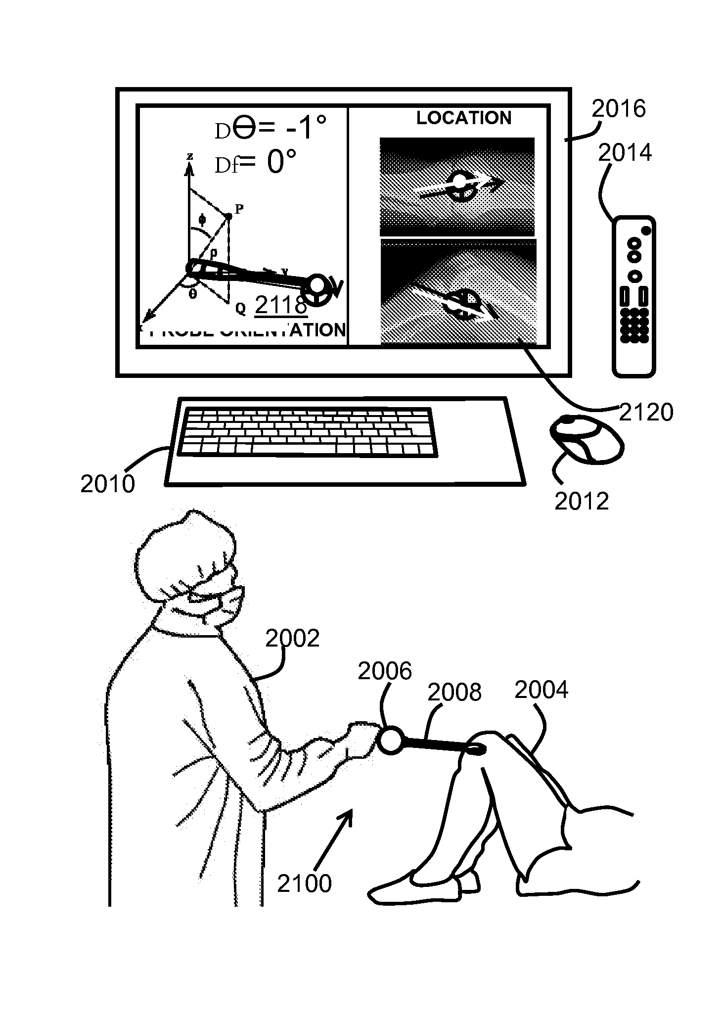
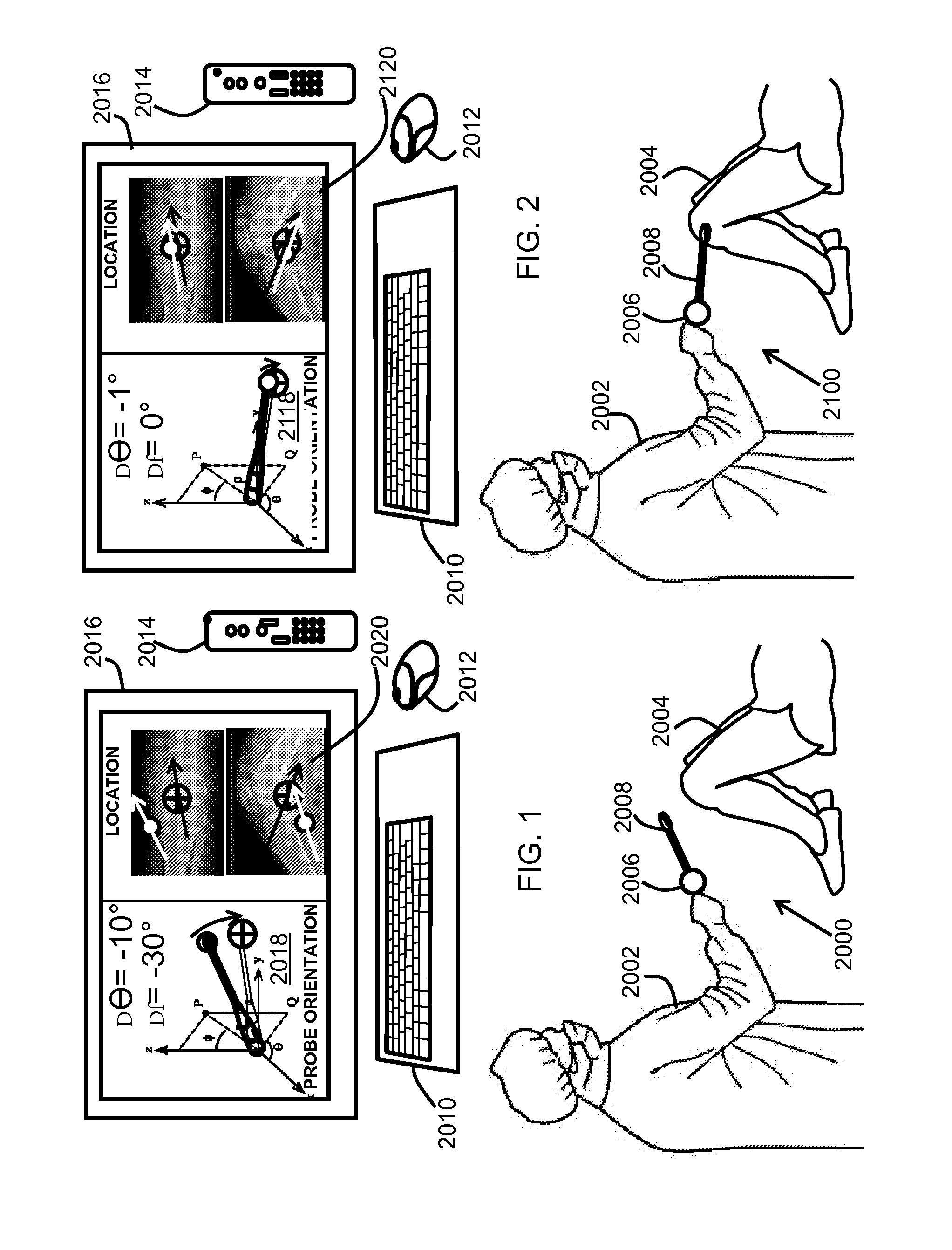
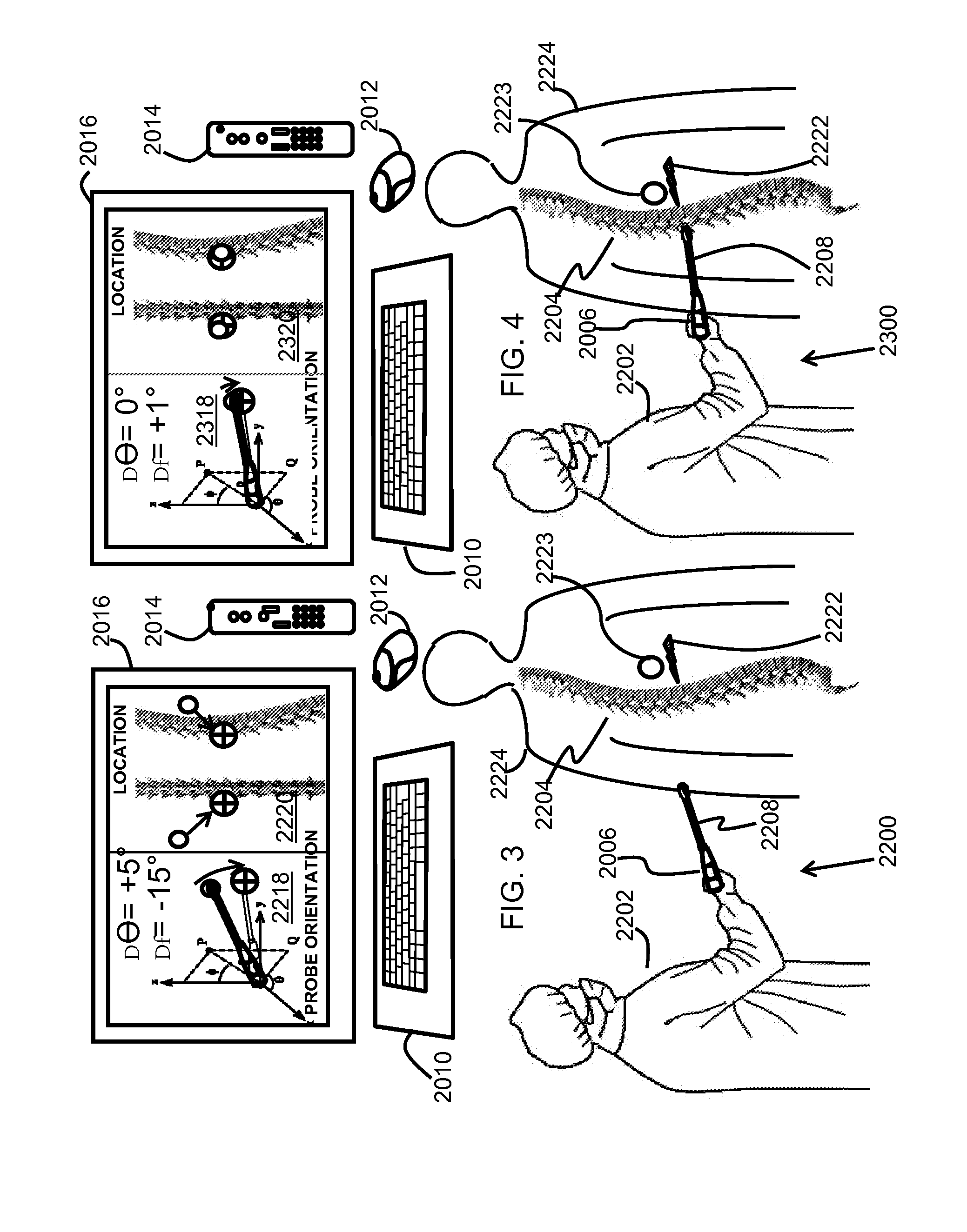
[0058]At least one embodiment is directed to a portable or handheld, wired or wireless dual tri-axial accelerometer device that facilitates replacement of a surgical instrument to a desired location, such an embodiment enables a cost effective alternative for performing many medical and surgical procedures. At least one embodiment is directed to a surgical tracking system that emits no harmful radiation, is light weight, requires minimal training, is inexpensive, flexible enough to support multiple procedures, can track real time motion of surgical devices and patients, and can include other biometric data sets.

[0059]Utilizing an accelerometer or other methods of the embodiments for surgical instrument placement reduces the invasiveness of many medical and surgical procedures without compromising the precision of locating probes...


PUM


Abstract

A prosthetic hip installation system comprising a reamer, an impactor, a tracking element, and a remote system. The tracking element can be integrated into the reamer or impactor for providing tracking data on the position or orientation. Alternatively, the tracking element can be housed in a separate module that can be coupled to either the reamer or impactor. The tracking element will couple to a predetermined location. Points in 3D space can be registered to provide a frame of reference for the tracking element or when the tracking element is moved from tool to tool. The tracking element sends data from the reamer or impactor wirelessly. The remote system receives the tracking data and can further process the data. A display on the remote system can support placement and orientation of the tool to aid in the installation of the prosthetic component.

Description

FIELD OF THE INVENTION[0001]The invention relates in general to medical and surgical procedures and more particularly to guiding medical devices to precise locations on or within a patient's body.BACKGROUND OF THE INVENTION[0002]Precisely positioning inserts, implants, or other medical devices, prostheses, prosthetic components, or topical application of medicines or anesthetics in or on patients' bodies depends on accurately locating structural features or anomalous structures on or within a patient's body. Continual progress has been made in the advancement and use of imaging equipment to guide the positioning of inserts, implants, or other medical devices, within patients' bodies. Noninvasive methods for locating internal structures of the body include ultrasound, X-rays, CT, and MRI equipment to locate anatomical features and anomalous structures within patients' bodies. Surgeons may use this data to create a pre-operative template to guide actions during the surgery.[0003]The u...

Claims


Application Information

Patent Timeline
IPC IPC(8): G09B23/28
CPCG09B23/286G09B23/28A61B34/20
Inventor STEIN, MARCVAUGHN, GLEN
Owner ORTHOSENSOR
Learn More