Rapid cleaning equipment for medical devices

A technology for cleaning equipment and medical equipment, applied in chemical instruments and methods, cleaning methods and utensils, cleaning methods using liquids, etc., and can solve the problems of wasting water resources, poor cleaning effect, and low cleaning efficiency.

Inactive Publication Date: 2018-01-19
深圳万研科技研发有限公司
View PDF6 Cites 16 Cited by
  • Summary
  • Abstract
  • Description
  • Claims
  • Application Information

AI Technical Summary

Benefits of technology

This patented describes an apparatus for cleaning medical equipment used by dentists during their workday activities such as teeth removal or rinses. It consists of three parts: a main machine (rotor), a cleaner unit, and two mobile units called wheels and cams. These components can be moved around within the housing while being driven together. Each component has its own unique features like a connection mechanism, a guided linkage, springs, and connections made up of gears. By adjusting these elements, the system allows smoothly spinning the cleaner over different areas of the patient's mouth without getting stuck due to friction caused by rubbing against surfaces. Additionally, there may include various mechanisms related to cleaning, including a filter basket assembly, a roller brush, and rails. Overall, this technology improves the performance and convenience of dental treatment machines.

Problems solved by technology

This patented technical problem addressed by this patent relates to improving the cleanliness and efficient removal of contaminants from medical tools during their reuse without causing environmental pollution due to excessive amounts of liquid waste generated through traditional methods such as rinses/discardings.

Method used


Image

  • Rapid cleaning equipment for medical devices
  • Rapid cleaning equipment for medical devices
  • Rapid cleaning equipment for medical devices

Examples


Embodiment 1

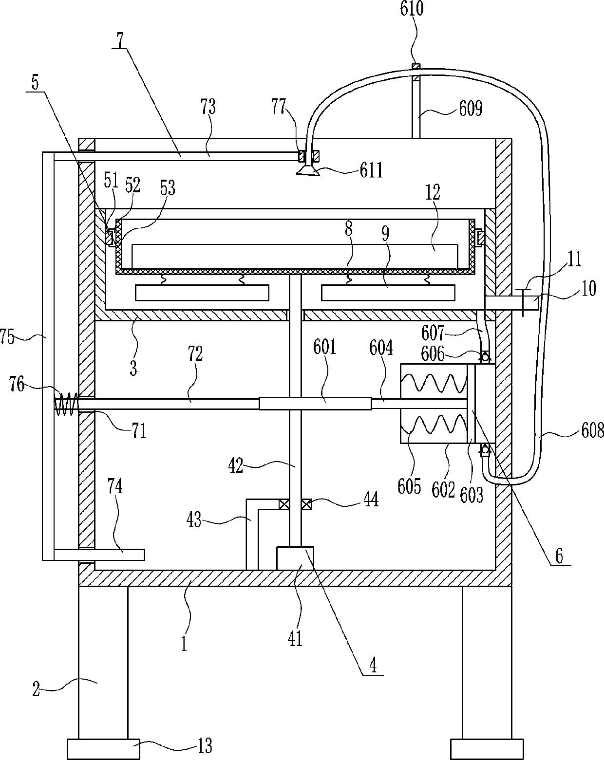
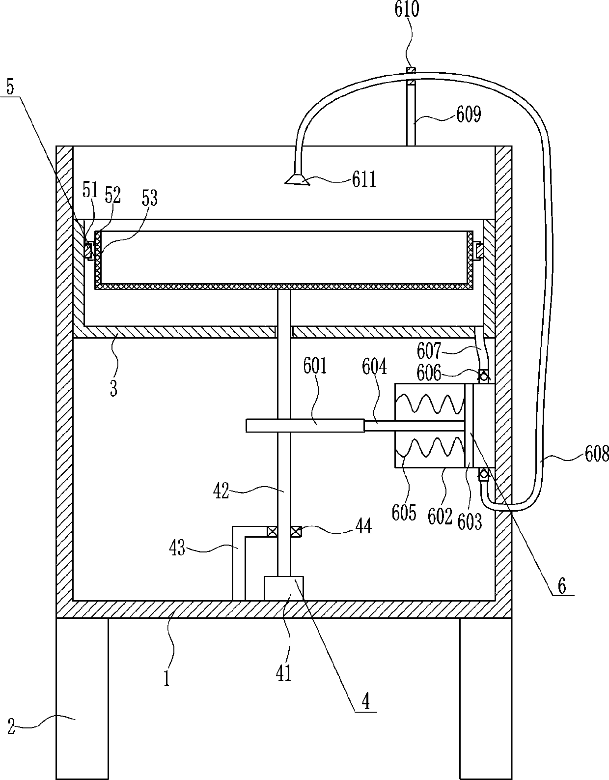
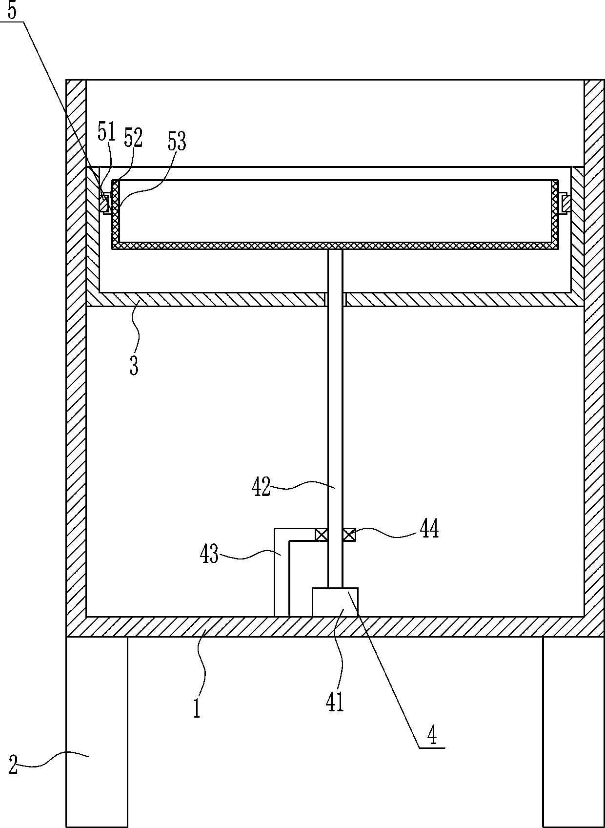
[0035] A kind of quick cleaning equipment for medical equipment, such as Figure 1-4 As shown, it includes a box body 1, legs 2, cleaning frame 3, driving device 4 and cleaning device 5, the four corners of the bottom of the box body 1 are connected with the legs 2, the top of the box body 1 is open, and the box body 1 A cleaning frame 3 is connected to the inner upper part, a driving device 4 is arranged in the middle of the inner bottom of the box body 1 , and a cleaning device 5 is arranged on the inner upper part of the cleaning frame 3 .

Embodiment 2

[0037] A kind of quick cleaning equipment for medical equipment, such as Figure 1-4 As shown, it includes a box body 1, legs 2, cleaning frame 3, driving device 4 and cleaning device 5, the four corners of the bottom of the box body 1 are connected with the legs 2, the top of the box body 1 is open, and the box body 1 A cleaning frame 3 is connected to the inner upper part, a driving device 4 is arranged in the middle of the inner bottom of the box body 1 , and a cleaning device 5 is arranged on the inner upper part of the cleaning frame 3 .

[0038] The driving device 4 includes a first motor 41, a rotating shaft 42, an L-shaped bar 43 and a bearing seat 44. The first motor 41 and the L-shaped bar 43 are installed in the middle of the inner bottom of the casing 1, and the first motor 41 is positioned at the bottom of the L-shaped bar 43. On the right side, the output shaft of the first motor 41 is connected with a rotating shaft 42, the top of the rotating shaft 42 runs thro...

Embodiment 3

[0040] A kind of quick cleaning equipment for medical equipment, such as Figure 1-4 As shown, it includes a box body 1, legs 2, cleaning frame 3, driving device 4 and cleaning device 5, the four corners of the bottom of the box body 1 are connected with the legs 2, the top of the box body 1 is open, and the box body 1 A cleaning frame 3 is connected to the inner upper part, a driving device 4 is arranged in the middle of the inner bottom of the box body 1 , and a cleaning device 5 is arranged on the inner upper part of the cleaning frame 3 .

[0041] The driving device 4 includes a first motor 41, a rotating shaft 42, an L-shaped bar 43 and a bearing seat 44. The first motor 41 and the L-shaped bar 43 are installed in the middle of the inner bottom of the casing 1, and the first motor 41 is positioned at the bottom of the L-shaped bar 43. On the right side, the output shaft of the first motor 41 is connected with a rotating shaft 42, the top of the rotating shaft 42 runs thro...


PUM


Abstract

The invention relates to cleaning equipment, in particular to rapid cleaning equipment for medical devices. According to the rapid cleaning equipment for the medical device, the cleaning efficiency ishigh, the cleaning effect is good, and waste of water sources is avoided. The rapid cleaning equipment for the medical device comprises a box body and the like. The four corners of the bottom of thebox body are all connected with supporting legs; the top of the box body is open; a cleaning frame is connected to the upper portion in the box body, and a driving device is arranged in the middle ofthe bottom in the box body; and a cleaning device is arranged on the upper portion in the cleaning frame. The driving device drives the cleaning device, a flushing device and a left-right moving device to operate, thus, the medical devices are fully and efficiently cleaned, and the effects that the cleaning efficiency is high, the cleaning effect is good, and waste of the water sources is avoidedare achieved.

Description


Claims


Application Information

Patent Timeline
Owner 深圳万研科技研发有限公司
Why Eureka
Try Eureka