Magnetic core conveying and turnover device and magnetic core arrangement machine provided with device

A technology of conveyor belts and magnetic cores, which is applied in the direction of conveyor objects, transportation and packaging, etc., can solve the problems of easy damage, affecting the processing yield, etc., and achieve the effect of improving safety and stability

Pending Publication Date: 2018-01-19
桐乡市佳顺自动化机械有限公司
View PDF11 Cites 2 Cited by
  • Summary
  • Abstract
  • Description
  • Claims
  • Application Information

AI Technical Summary

Problems solved by technology

However, for a large-sized magnetic core, it is easy to make the corner of the magnetic core collide with the side of the U-shaped groove when it slides down in the twisted V-shaped groove and U-shaped groove. Very easy to be damaged and scrapped, affecting the processing yield

Method used


Image

  • Magnetic core conveying and turnover device and magnetic core arrangement machine provided with device
  • Magnetic core conveying and turnover device and magnetic core arrangement machine provided with device
  • Magnetic core conveying and turnover device and magnetic core arrangement machine provided with device

Examples


Embodiment 1

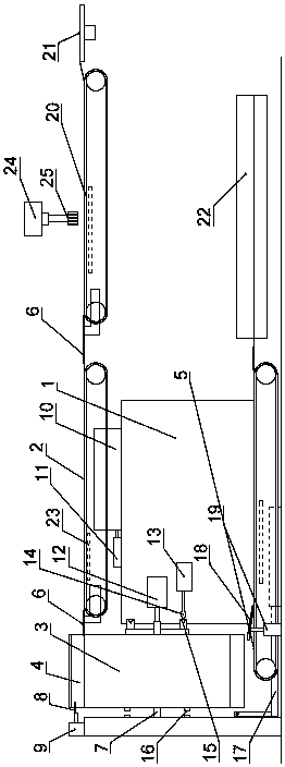
[0022] A magnetic core conveying and turning device described in this embodiment includes a frame 1, on which a No. 1 conveyor belt 2, a No. 2 conveyor belt 5 and a turning frame 3 are respectively arranged, and the turning frame 3 is rotated by rotating The shaft 7 is arranged on the frame 1, and the outer edge of the turning frame 3 is provided with two linear cavities 4 for accommodating the arrangement of the magnetic cores. When the frame 3 is rotated to a certain position, the linear cavity 4 is docked, and the conveying directions of the No. 1 conveyor belt 2 and the No. 2 conveyor belt 5 are consistent with the axial direction of the linear cavity 4; the No. 1 conveyor belt 2 is used to connect the magnetic The core is input into the linear cavity 4 of the turning frame 3, and the second conveyor belt 5 is used to transport the magnetic core in the linear cavity 4 to the arrangement device 22; 4 is provided with an induction switch 8, and a transition plate 6 is provid...

Embodiment 2

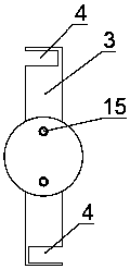
[0024] like figure 1 , figure 2 As shown in the figure, a magnetic core conveying and turning device described in this embodiment includes a frame 1, and a No. 1 conveyor belt 2, a No. 2 conveyor belt 5 and a turning frame 3 are respectively arranged on the frame 1. The turning frame 3 is arranged on the frame 1 through the rotating shaft 7, the outer edge of the turning frame 3 is provided with two linear cavities 4 for accommodating the arrangement of the magnetic cores, the No. 1 conveyor belt 2, the No. 2 conveyor belt 5 They are respectively docked with the linear cavity 4 when the turning frame 3 is rotated to a certain position, and the conveying direction of the No. 1 conveyor belt 2 and the No. 2 conveyor belt 5 is consistent with the axial direction of the linear cavity 4; the No. 1 conveyor belt 2 is used for When the magnetic core is input into the linear cavity 4 of the turning frame 3 , the No. 2 conveyor belt 5 is used to transport the magnetic core in the lin...

Embodiment 3

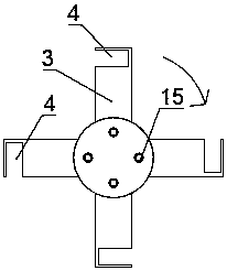
[0032] like figure 1 , image 3 As shown in the figure, a magnetic core conveying and turning device described in this embodiment is different from Embodiment 2 in that: the turning frame 3 is provided with four linear cavities 4, that is, two groups, each of which has two straight lines. The cavity bodies 4 are arranged at both ends of the turning frame 3 in the diameter direction.


PUM


Abstract

The invention relates to the field of magnetic core arrangement equipment, in particular to a magnetic core conveying and turnover device. The magnetic core conveying and turnover device comprises a rack. A first conveying belt, a second conveying belt and a turnover frame are arranged on the rack. The turnover frame is arranged on the rack through a rotary shaft. One or more linear cavities allowing magnetic cores to be arranged are formed in the outer edge of the turnover frame. The first conveying belt and the second conveying belt are in butt joint with the linear cavities when the turnover frame rotates to a certain position correspondingly, and the conveying direction of the first conveying belt and the conveying direction of the second conveying belt are consistent with the axial direction of the linear cavities. A magnetic core arrangement machine provided with the magnetic core conveying and turnover device further comprises a third conveying belt, a rotating disc and a magnetic core arrangement device. According to the magnetic core conveying and turnover device and the magnetic core arrangement machine provided with the device, by means of the design of the turnover frame, turnover in the magnetic core arrangement process is achieved, the magnetic cores cannot be damaged in the turnover process, and safety and stability are remarkably improved.

Description

technical field [0001] The invention relates to the field of magnetic core arranging equipment, in particular to a magnetic core conveying and turning device and a magnetic core arranging machine with the same. Background technique [0002] In the prior art, after the magnetic core is pressed and formed, the magnetic core is turned over by a combination of twisted V-shaped grooves and U-shaped grooves. However, when the large-sized magnetic core slides down in the twisted V-shaped groove and U-shaped groove, it is easy for the corner of the magnetic core to hit the side of the U-shaped groove. Since the magnetic core material is relatively brittle, during the impact process It is very easy to be damaged and scrapped, which affects the processing yield. SUMMARY OF THE INVENTION [0003] The purpose of the present invention is to provide a magnetic core conveying and turning device and a magnetic core arranging machine with the device, which is simple in structure and can e...

Claims


Application Information

Patent Timeline
Patent Type & Authority Applications(China)
IPC IPC(8): B65G47/52B65G47/248
Inventor 赵利忠
Owner 桐乡市佳顺自动化机械有限公司
Why Eureka
Try Eureka