Compression mechanism of compressor

A compression mechanism and compressor technology, which is applied in the field of compressors, can solve problems such as carbonization, size reduction, and seal failure, and achieve the effects of optimizing force and sealing structure, improving service life, and good sealing performance

Active Publication Date: 2018-01-19
HUAZHONG UNIV OF SCI & TECH
View PDF6 Cites 0 Cited by
  • Summary
  • Abstract
  • Description
  • Claims
  • Application Information

AI Technical Summary

Problems solved by technology

[0003] Piston rings and packings have openings, and there is a leakage path in principle. Good sealing performance can only be guaranteed at high moving speeds, and the leakage is serious at low moving speeds, so it cannot be used in high-pressure situations
In addition, due to the special structure of the piston ring and packing, its size cannot be reduced to less than 10mm (diameter), so it cannot be applied to a small high-pressure compressor
[0004] Traditional engineering plastic sealing rings have good sealing performance in principle and can perform high-pressure sealing. However, in high-temperature, high-pressure and dry friction situations, engineering plastics are prone to deformation, carbonization, and severe wear, resulting in seal failure and affecting The service life of the whole machine

Method used


Image

  • Compression mechanism of compressor
  • Compression mechanism of compressor
  • Compression mechanism of compressor

Examples


Embodiment Construction

[0029] In order to make the object, technical solution and advantages of the present invention clearer, the present invention will be described in further detail below in conjunction with the accompanying drawings and embodiments. It should be understood that the specific embodiments described here are only used to explain the present invention, not to limit the present invention. In addition, the technical features involved in the various embodiments of the present invention described below can be combined with each other as long as they do not constitute a conflict with each other.

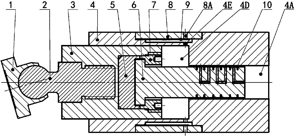
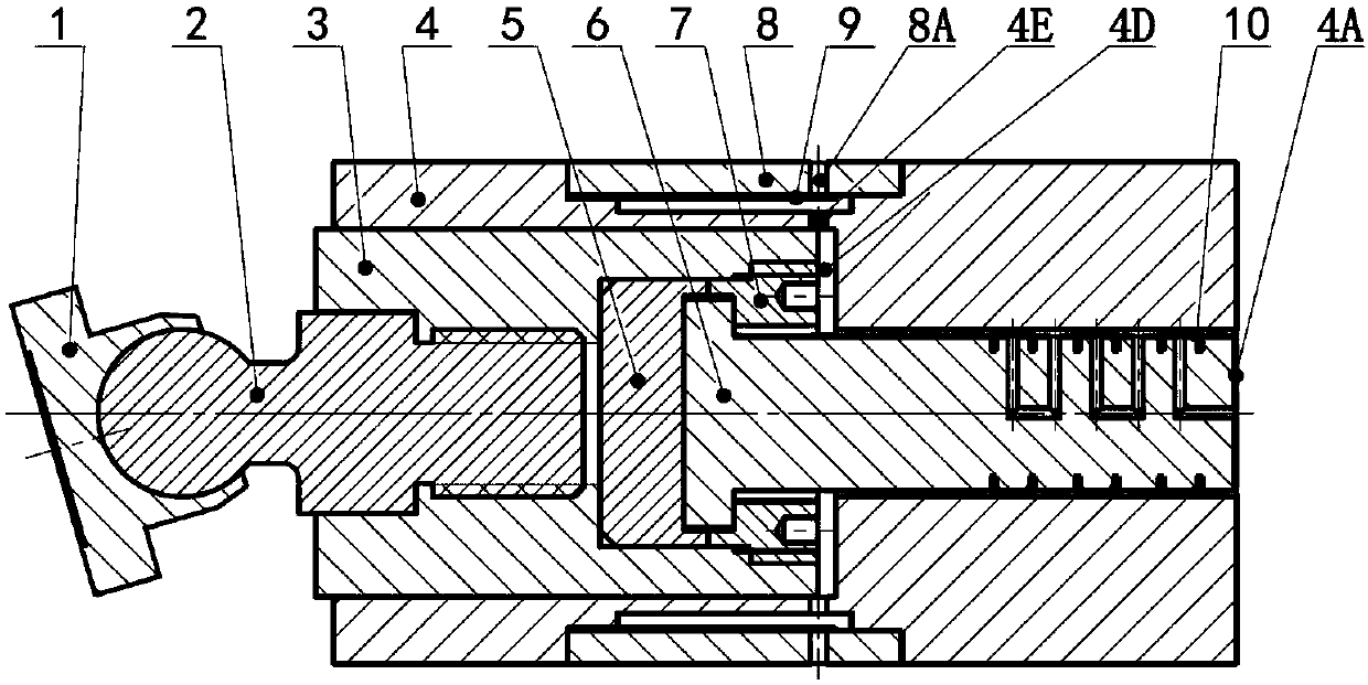
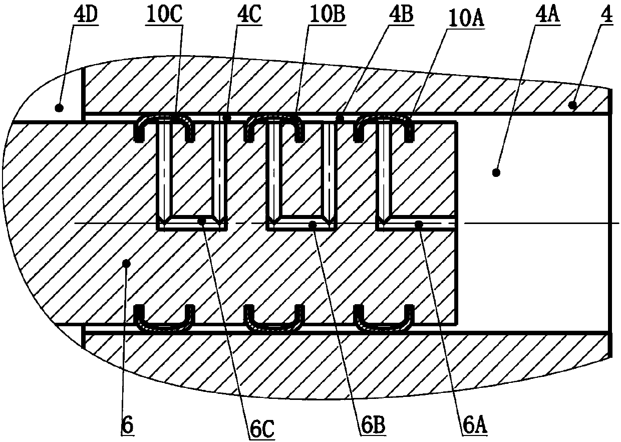
[0030] refer to Figure 1 to Figure 5 , a compression mechanism of a compressor, including a sliding shoe 1, a connecting rod 2, a first piston 3, a second piston 6, a left limiting block 5, a right limiting block 7, a cylinder liner 4 and a U-shaped sealing strip 10, in,

[0031] The left end ball of described connecting rod 2 is hinged on the described shoe 1, and the right end of described ...


PUM


Abstract

The invention belongs to the field of compressor, and discloses a compression mechanism of a compressor. The compression mechanism of the compressor comprises a sliding shoe, a connecting rod, a firstpiston, a second piston, a left limiting block, a right limiting block, a cylinder sleeve and a U-shaped sealing strip, wherein the left end of the connecting rod is hinged to the sliding shoe, and the right end of the connecting rod stretches into the left end of the first piston; a limiting block accommodating hole is formed in the right end of the first piston, and the left limiting block andthe right limiting block are arranged in the limiting block accommodating hole; the second piston comprises a second piston main body and a shaft shoulder arranged at the left end of the second pistonmain body; a compression cavity is formed in the right end of the cylinder sleeve; and the second piston is located in the cylinder sleeve, a gap exists between the second piston main body and the inner wall of the cylinder sleeve and forms an annular cavity, and the U-shaped sealing strip is arranged at the position of the annular cavity. According to the compression mechanism of the compressor,the stress and seal structure is optimized, high-pressure sealing can be achieved easily, and meanwhile, the service life of assemblies is prolonged.

Description

technical field [0001] The invention belongs to the field of compressors, and more specifically relates to a compression mechanism of a compressor. Background technique [0002] Piston compressors are widely used in many sectors of national economy and national defense construction, especially in petroleum, chemical, power and other industrial fields, which have become indispensable key equipment. The sealing performance of the piston compressor determines the efficiency and working pressure of the compressor. In the piston compressor, the piston and cylinder assembly play a role in sealing the high-pressure compressed gas, which is an extremely critical component in the piston compressor. The piston The traditional sealing structures in the compressor are piston rings, fillers or engineering plastic sealing rings, and these sealing structures have the following deficiencies. [0003] Piston rings and packings have openings, and there is a leakage path in principle. Good se...

Claims


Application Information

Patent Timeline
Patent Type & Authority Applications(China)
IPC IPC(8): F04B39/00
Inventor 邓亦攀刘银水苗娜吴德发庞浩
Owner HUAZHONG UNIV OF SCI & TECH
Why Eureka
Try Eureka