Electro-hydraulic driving swing mechanism

A swing mechanism, electro-hydraulic technology, applied in mechanical equipment, fluid pressure actuating devices, servo motors, etc., can solve the problems of uneven swing speed, difficult maintenance, small torque, etc., to achieve simple driving mode, high control accuracy, The effect of large driving torque

Pending Publication Date: 2018-01-19
YANSHAN UNIV
View PDF0 Cites 2 Cited by
  • Summary
  • Abstract
  • Description
  • Claims
  • Application Information

AI Technical Summary

Problems solved by technology

When the crank rocker mechanism is used to change the rotary motion into swing, when the rotary motion is a uniform rotation, the swing speed is uneven, and the movement time in the two directions of the swing is different; the rotary cam mechanism is used to convert the rotation When swinging, the groove on the rotary surface is difficult to ensure the uniform speed of swinging and difficult to process; the swing is realized by controlling the positive and negative rotation of the input shaft, which has relatively high requirements for the control part, and it is usually difficult to realize the swing of the output shaft The speed is stable; when the gear mechan

Method used


Image

  • Electro-hydraulic driving swing mechanism
  • Electro-hydraulic driving swing mechanism
  • Electro-hydraulic driving swing mechanism

Examples


Embodiment Construction

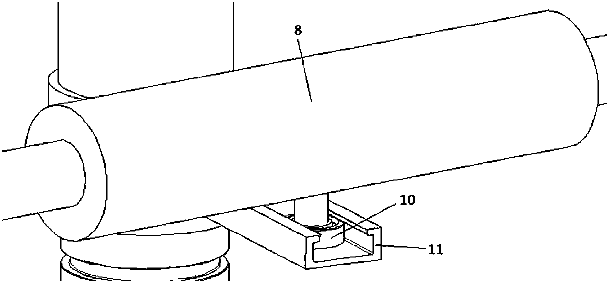
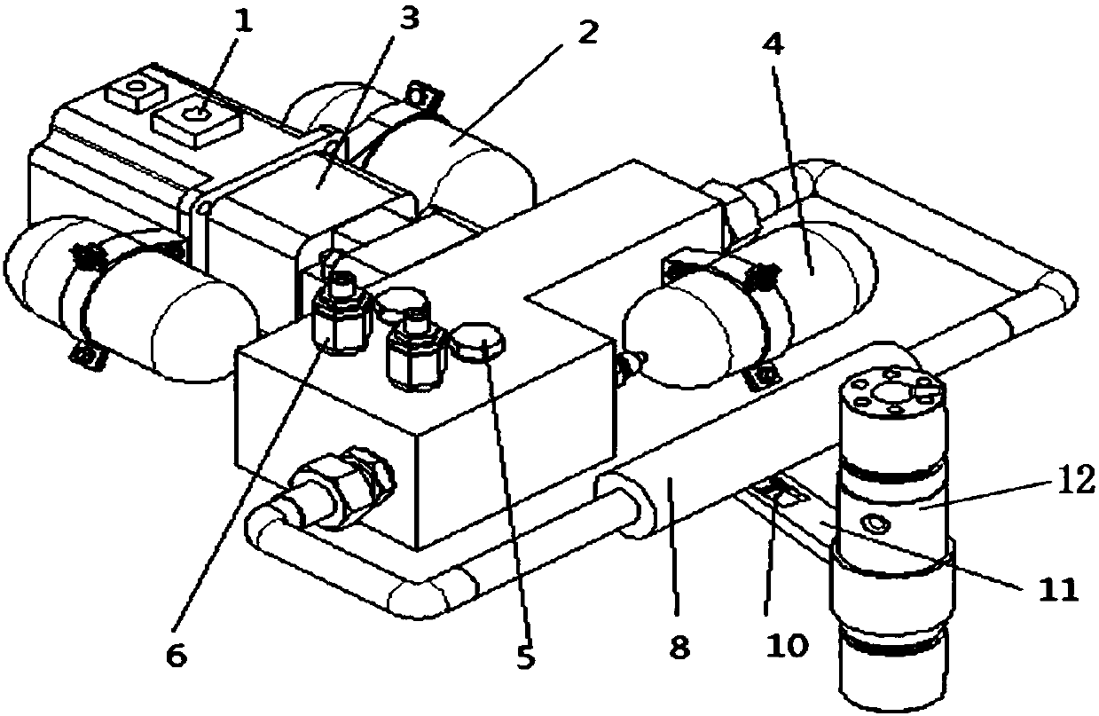
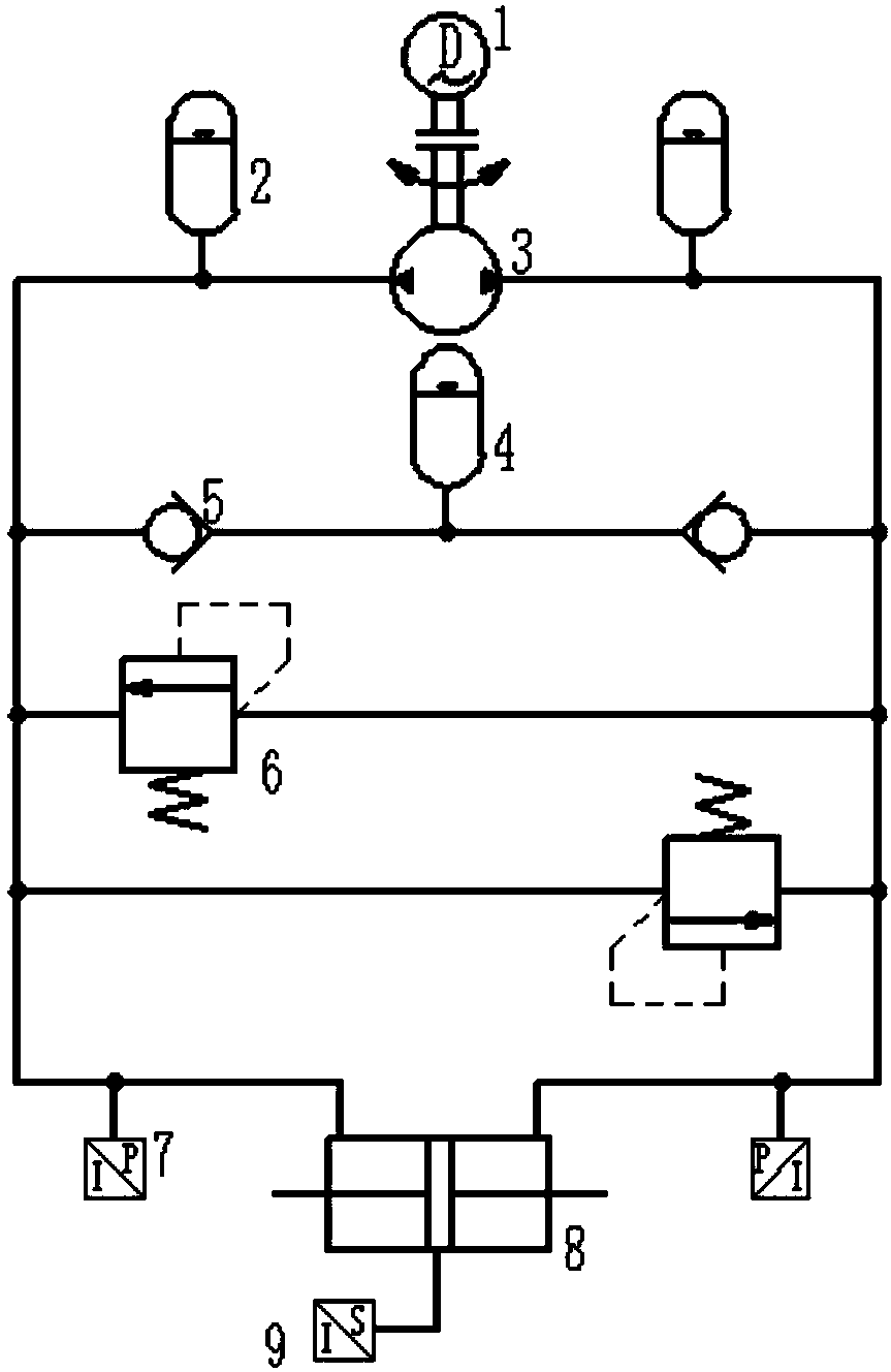
[0016] exist figure 1 and figure 2 In the schematic diagram of the electro-hydraulic drive swing mechanism shown, the servo motor 1 is connected to the two-way quantitative pump 3, the two outlets of the two-way quantitative pump are connected to the outlet of a one-way valve 5, and the inlets of the two one-way valves are connected to the Charge accumulator 4 is connected. A hydraulic oil accumulator 2 is respectively arranged on the two pipelines connecting the two check valves with the bidirectional quantitative pump, and the two hydraulic oil accumulators are respectively connected to the bidirectional quantitative pump through hoops. The two working oil ports of the two-way quantitative pump are also connected in parallel with two safety valves 6 respectively. In order to reduce the volume and facilitate the connection, the two one-way valves and the two safety valves are collectively arranged in one box. The two-way quantitative pumps are respectively connected to th...


PUM


Abstract

The invention provides an electro-hydraulic driving swing mechanism. The electro-hydraulic driving swing mechanism is mainly characterized in that a servo motor is connected with a two-way constant displacement pump, and each outlet of the two-way constant displacement pump is connected with an outlet of a one-way valve; inlets of the two one-way valves are connected with an oil replenishing energy accumulator; the two-way constant displacement pump is connected with oil holes at the two ends of a hydraulic cylinder through pipelines provided with pressure sensors; the hydraulic cylinder is ofa double outlet rod structure and is provided with a connecting mechanism for connecting a swing shaft and the hydraulic cylinder, that is to say, a cylinder barrel of the hydraulic cylinder is connected with an inner ring of a rolling bearing through a connecting piece, and one axis of the rolling bearing is perpendicular to the cylinder barrel; and an outer ring of the rolling bearing is arranged in a sliding groove of a rocker rod, the other end of the rocker rod is connected with the swing shaft, and the length of the rocker rod is determined according to the rotating angle of the swing shaft. According to the electro-hydraulic driving swing mechanism, response is quick, the controlling precision of the swing angle is high, the structure is simple, driving torque is large, and requirements for small size in high-grade high-precision and advanced special occasions can be met.

Description

technical field [0001] The invention relates to an oscillating mechanism, in particular to a device integrating an electro-hydraulic drive and a mechanical oscillating mechanism. Background technique [0002] The existing oscillating mechanism realizes clockwise and counterclockwise oscillating mainly through several methods such as a crank rocker mechanism, a rotary surface cam mechanism, forward and reverse control of an input shaft, or a gear mechanism. When the crank rocker mechanism is used to change the rotary motion into swing, when the rotary motion is a uniform rotation, the swing speed is uneven, and the movement time in the two directions of the swing is different; the rotary cam mechanism is used to convert the rotation When swinging, the groove on the rotary surface is difficult to ensure the uniform speed of swinging and difficult to process; the swing is realized by controlling the positive and negative rotation of the input shaft, which has relatively high re...

Claims


Application Information

Patent Timeline
IPC IPC(8): F15B1/04F15B11/08F15B13/04
Inventor 赵静一李文雷刘杰茹强司少朋王少晨赵伟哲
Owner YANSHAN UNIV
Why Eureka
Try Eureka