
Current detection method and device based on magnetic modulation technology

A current detection device and current detection technology, applied in the direction of measurement using digital measurement technology, can solve the problem that the accuracy, stability and reliability cannot meet the requirements, the residual current measurement field is not widely used, and the non-sinusoidal current detection accuracy lower problem

Inactive Publication Date: 2018-01-19
SHANGHAI SHENGXIANG ELECTRONICS SCI & TECH CO LTD
View PDF4 Cites 11 Cited by
  • Summary
  • Abstract
  • Description
  • Claims
  • Application Information

AI Technical Summary

Problems solved by technology

[0005] The first type of non-contact detection technology converts the magnetic field generated by the current into a measurable electrical signal through physical effects such as the Hall effect, giant magneto-impedance effect, and tunneling magneto-impedance effect. The accuracy, stability and reliability of this type of detection method Therefore, this technology is not widely used in the field of residual current measurement
[0006] The second type of non-contact detection technology is based on the principle of electromagnetic induction. It detects the magnitude of the measured current flowing through the current-carrying conductor through the induced current generated by the secondary coil on the current transformer surrounding the current-carrying conductor under test. The detection method cannot detect DC current, and the current detection accuracy for non-sinusoidal waves is also low
But its disadvantage is that the circuit is very complicated. At present, most products of this type of technology need hundreds of electronic components to realize the function, the manufacturing cost is high, and the overall reliability of the circuit is low.

Method used

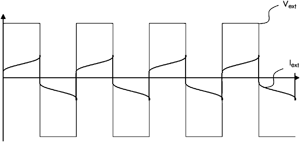
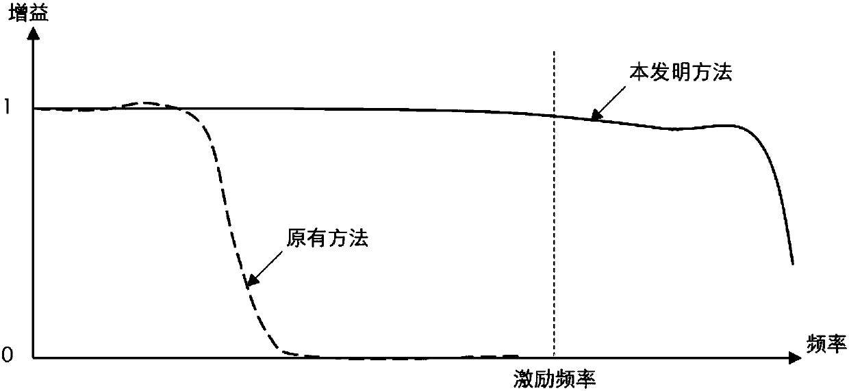

Image

  • Current detection method and device based on magnetic modulation technology
  • Current detection method and device based on magnetic modulation technology
  • Current detection method and device based on magnetic modulation technology

Examples


Embodiment Construction

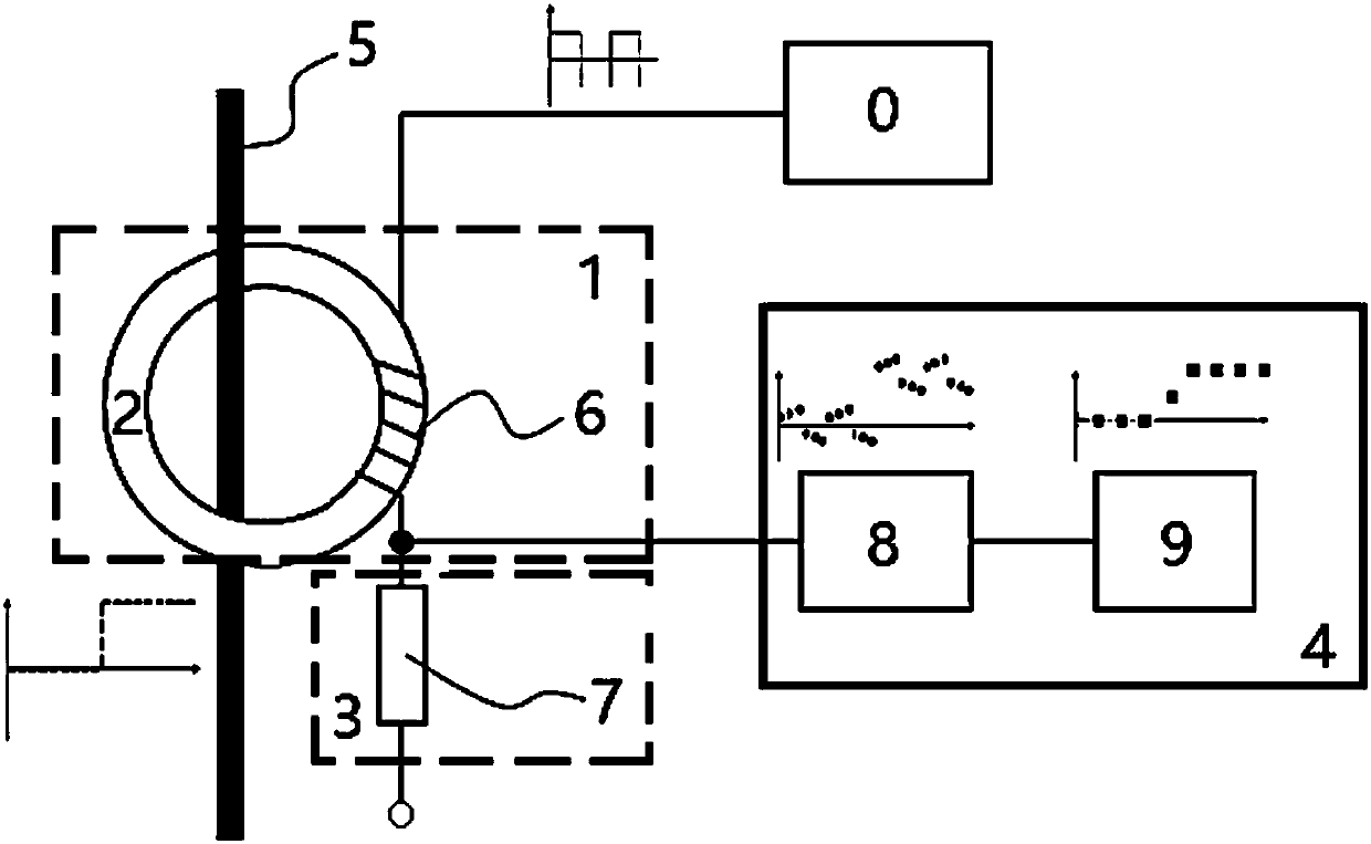
[0023] Such as figure 1 As shown, this embodiment includes: at least one current-carrying conductor 5 to be tested, a signal generating mechanism 0 for generating a magnetically modulated carrier wave, a modulation mechanism 1, a signal acquisition mechanism 3 and a signal demodulation mechanism 4, wherein: the signal generating mechanism 0 Generate a modulation signal and output it to the modulation mechanism 1, the current-carrying conductor 5 to be tested passes through the modulation mechanism 1, and outputs the modulation signal to the signal acquisition mechanism 3, and the signal demodulation mechanism 4 performs analog-to-digital conversion on the voltage on the signal acquisition mechanism 3 The current on the current-carrying conductor to be tested is obtained after dimension reduction.

[0024] The modulation mechanism 1 includes an exciting winding 6 and a closed magnetically conductive medium 2, wherein: the exciting winding 6 is arranged on the closed magneticall...


PUM


Abstract

A current detection method and device based on magnetic modulation technology is disclosed. An excitation winding with a closed magnetic medium acts as a modulator at a sensing end to modulate a current to be detected on at least one current-carrying conductor to be detected to a periodic carrier signal, a digital domain signal is obtained through analog-digital conversion at a detection end, andthen a characteristic value representing the current information on the current-carrying conductor to be detected is obtained through dimension reduction processing, wherein: the frequency of the digital domain signal is an integer multiple of the frequency of the carrier signal. According to the invention, sampling can be conducted at a specific time to avoid the adverse effects of different saturation depths without the need of maintaining a relatively constant excitation saturation depth by means of closed-loop feedback. The determined excitation signal of the open-loop control can be usedand a closed-loop control loop and a low-pass filter are not required.

Description

technical field [0001] The present invention relates to a technology in the field of current detection, in particular to a current detection method and device based on magnetic modulation technology. Background technique [0002] Current detection technology is widely used in various industrial and civil occasions. Its main function is to monitor the working current of various electrical appliances and the current of the power supply circuit, or provide current feedback information for the control system. The residual current detection technology is mainly used to ensure personal safety and prevent potential safety hazards caused by leakage. In addition, the residual current detection technology with a large detection current is also used to protect the safety of electrical appliances and power supply circuits, and prevent property losses caused by ground faults. [0003] Existing current and residual current detection technology can be divided into two types: contact type ...

Claims


Application Information

Patent Timeline
IPC IPC(8): G01R19/25
Inventor 吴笛
Owner SHANGHAI SHENGXIANG ELECTRONICS SCI & TECH CO LTD
Learn More