Eureka AIR delivers breakthrough ideas for toughest innovation challenges, trusted by R&D personnel around the world.

Time difference, frequency difference and frequency difference change rate joint estimation method

A technology of joint estimation and frequency difference estimation, applied in joint estimation of frequency difference change rate, frequency difference, and time difference, can solve problems such as three-dimensional search calculation complexity, achieve the effect of improving accuracy, improving positioning accuracy, and enriching positioning parameters

Active Publication Date: 2018-01-19
TSINGHUA UNIV
View PDF5 Cites 23 Cited by
  • Summary
  • Abstract
  • Description
  • Claims
  • Application Information

AI Technical Summary

Problems solved by technology

Since the time difference, frequency difference, and frequency difference change rate are unknown in the actual observation process, it is necessary to complete the joint estimation of the time difference, frequency difference, and frequency difference change rate to solve the computational complexity caused by the three-dimensional search in the joint estimation process degree problem

Method used


Image

  • Time difference, frequency difference and frequency difference change rate joint estimation method
  • Time difference, frequency difference and frequency difference change rate joint estimation method
  • Time difference, frequency difference and frequency difference change rate joint estimation method

Examples


Embodiment Construction

[0038] The present invention will be described in detail below in conjunction with the accompanying drawings. However, it should be understood that the accompanying drawings are provided only for better understanding of the present invention, and they should not be construed as limiting the present invention.

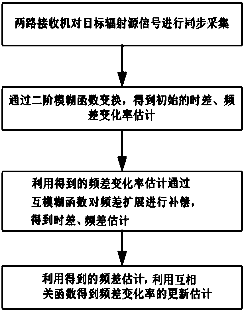
[0039] Such as figure 1 As shown, the joint estimation method of time difference, frequency difference and frequency difference rate of change provided by the present invention includes the following contents:

[0040] 1. The two receivers collect the signal of the target radiation source synchronously in time, and the collected digital signals are respectively s 1 (n) and s 2 (n):

[0041] the s 1 (n)=s(n)+n 1 (n)-N / 2≤n≤N / 2

[0042]

[0043] In the formula, s(n) represents the target radiation source signal, n 1 (n) and n 2 (n) represent the noise signal of the receiver respectively, τ represents the arrival time difference of the signals collected by the tw...


PUM


Abstract

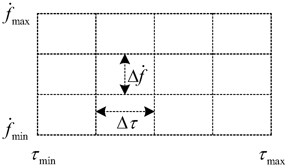
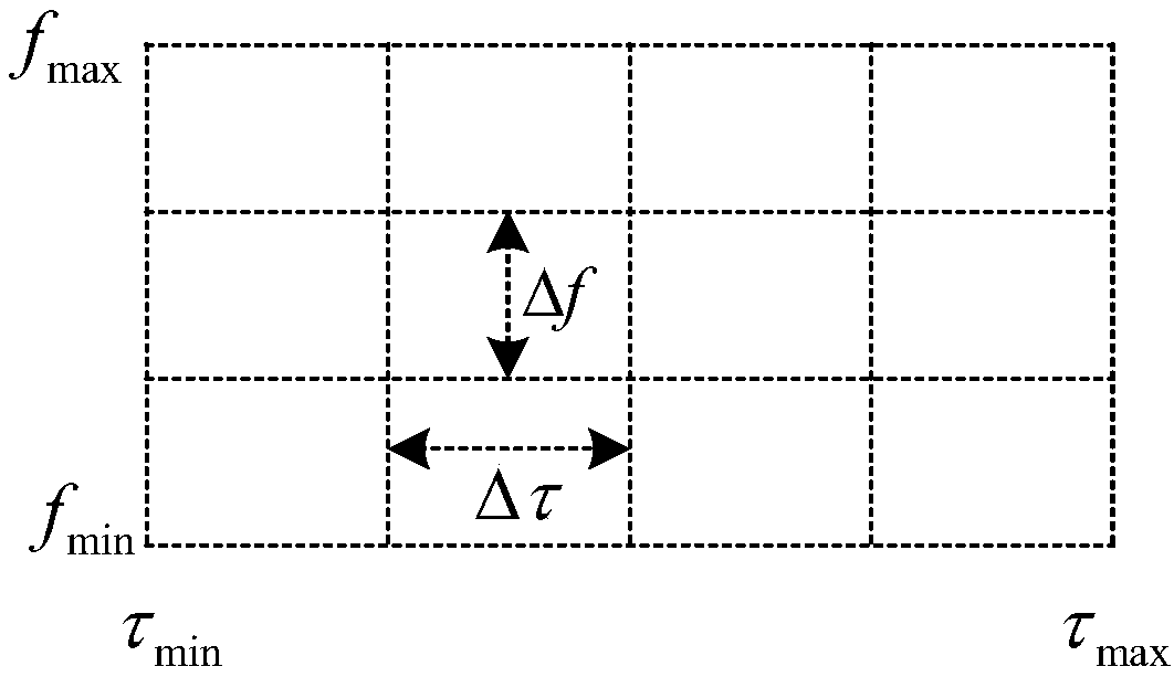
The invention relates to a time difference, frequency difference and frequency difference change rate joint estimation method which comprises the following steps: (1) two receivers synchronously collect a target radiation source signal, wherein the digital signals collected are respectively s1(n) and s2(n); (2) mesh generation is carried out on the target radiation source signal in the time difference range and in the frequency difference change rate range respectively, a second-order ambiguity function H (Tau, f) is calculated for each mesh point, and the initial estimate (Tau-^, f-.^) of time difference and frequency difference change rate is obtained by searching for the module values of the second-order ambiguity functions H (Tau, f) of the mesh points; (3) compensation is made for frequency difference expansion through a cross ambiguity function CAF (Tau, f) according to the initial estimate f-.^ of frequency difference change rate to get new time difference estimate and frequencydifference estimate; and (4) new frequency difference change rate estimate is obtained through a frequency difference change rate cross correlation function according to the new frequency differenceestimate. The method of the invention is applicable to the passive location of time and frequency difference under high dynamic conditions.

Description

technical field [0001] The invention relates to a joint estimation method of time difference, frequency difference and frequency difference change rate, and relates to the technical field of time-frequency difference passive positioning. Background technique [0002] Passive positioning is a positioning technology that determines the position of a radiation source by receiving its own radiation signal. Because this method has strong anti-interference ability and good concealment, it has been paid attention to and widely used by various countries in recent years. The common method of passive positioning is to use the time difference (time difference) and Doppelganger The spatial geometric position of the target radiation source can be determined by information such as Le frequency difference (frequency difference). [0003] Existing time difference and frequency difference estimation methods only consider the observations of time difference and frequency difference. Under t...

Claims


Application Information

Patent Timeline
IPC IPC(8): G01S11/02
Inventor 黄振胡德秀张尚煜何加智
Owner TSINGHUA UNIV
Why Eureka
Eureka Blog
Learn More