
Sliding mode control method of input saturated spacecraft attitude terminal

A tracking control, terminal sliding mode technology, applied in the direction of adaptive control, general control system, control/regulation system, etc., can solve problems such as control performance degradation, system instability, and infinite control input.

Active Publication Date: 2018-01-19
XIANGTAN UNIV
View PDF5 Cites 7 Cited by
  • Summary
  • Abstract
  • Description
  • Claims
  • Application Information

AI Technical Summary

Problems solved by technology

However, the traditional TSM controller has two disadvantages: one is that when the system is far from the equilibrium state, the TSM controller converges slower than the traditional linear hyperplane sliding mode control; the other is the singularity problem, which often causes the control input to be infinite
The actuators of actual spacecraft have input amplitude limitations. If the input saturation problem of the controller is not considered, the control performance of the entire control system will be degraded, and even the entire system will be unstable.
[0009] Therefore, it is necessary to propose a new control method that can overcome the unwinding-free finite-time control and finite-time stability problems in the case of actuator saturation

Method used


Image

  • Sliding mode control method of input saturated spacecraft attitude terminal
  • Sliding mode control method of input saturated spacecraft attitude terminal
  • Sliding mode control method of input saturated spacecraft attitude terminal

Examples


Embodiment 1

[0154] Among them, the compensation known bounded control method includes the following steps:

[0155] Step 1. Establish the spacecraft attitude dynamic equation;

[0156] The definition of spacecraft attitude dynamic equation is shown in formulas (1)-(3):

[0157]

[0158]

[0159]

[0160] ω∈R 3×1 is the angular velocity of the spacecraft in the body coordinate system, R∈SO(3) is the rotation matrix that transforms the body coordinate system into the inertial coordinate system, u∈R 3×1 and d ∈ R 3×1 are the control torque and external disturbance torque respectively, J∈R 3×3 is the inertia matrix;

[0161] Step 2. Consider external disturbance attitude error:

[0162] Using the defined rotation matrix error and angular velocity error, the relative differential equation formula (4)-(6) of attitude error can be obtained

[0163]

[0164]

[0165]

[0166] and represent the rotation matrix error and angular velocity error, respectively, where R d ∈...

Embodiment 2

[0237] Hyperbolic Tangent Function and Auxiliary System Control Method

[0238] It includes the following steps:

[0239] Step 1. Establish the spacecraft attitude dynamic equation;

[0240] The definition of spacecraft attitude dynamic equation is shown in formulas (23)-(25):

[0241]

[0242]

[0243]

[0244] ω∈R 3×1 is the angular velocity of the spacecraft in the body coordinate system, R∈SO(3) is the rotation matrix that transforms the body coordinate system into the inertial coordinate system, u∈R 3×1 and d ∈ R 3×1 are the control torque and external disturbance torque respectively, J∈R 3×3 is the inertia matrix.

[0245] Step 2. Introduce external disturbance attitude error:

[0246]Using the defined rotation matrix error and angular velocity error, the relative differential equation formulas (26)-(28) of the attitude error can be obtained;

[0247]

[0248]

[0249]

[0250] and represent the rotation matrix error and angular velocity erro...


PUM


Abstract

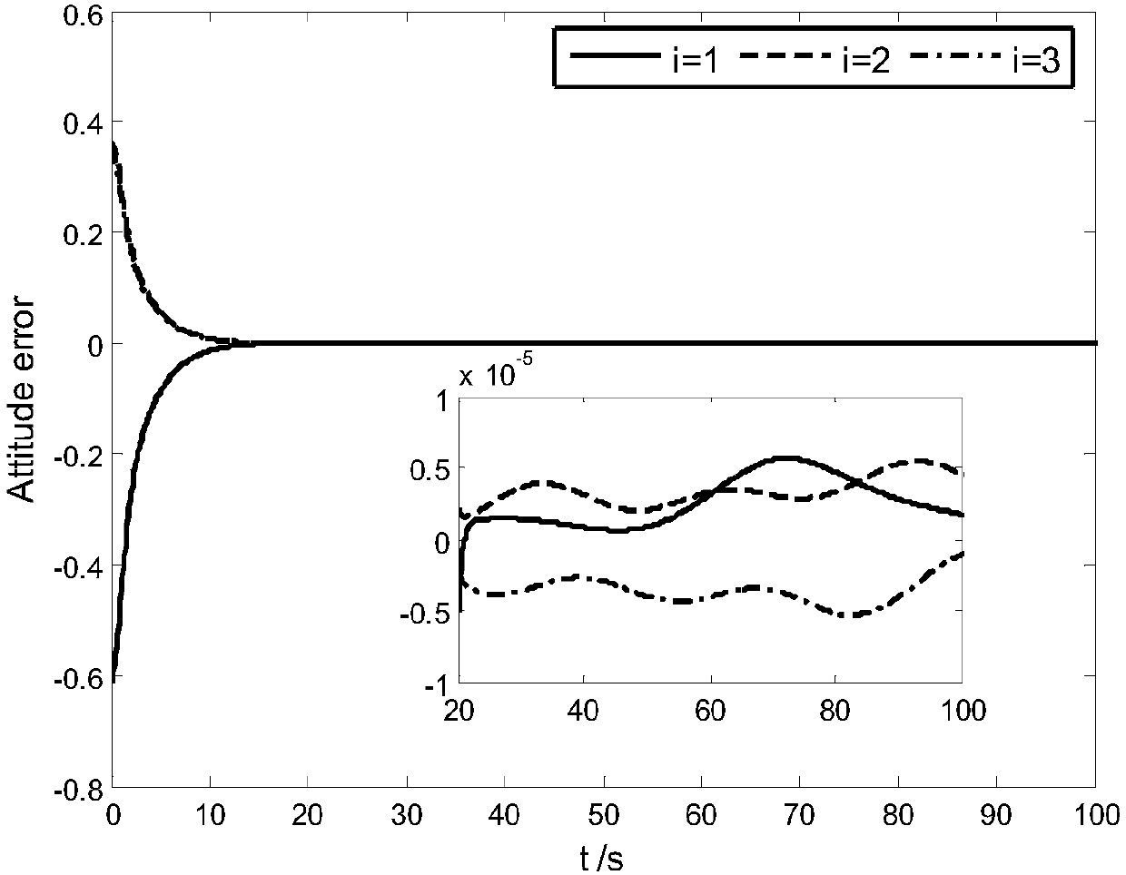
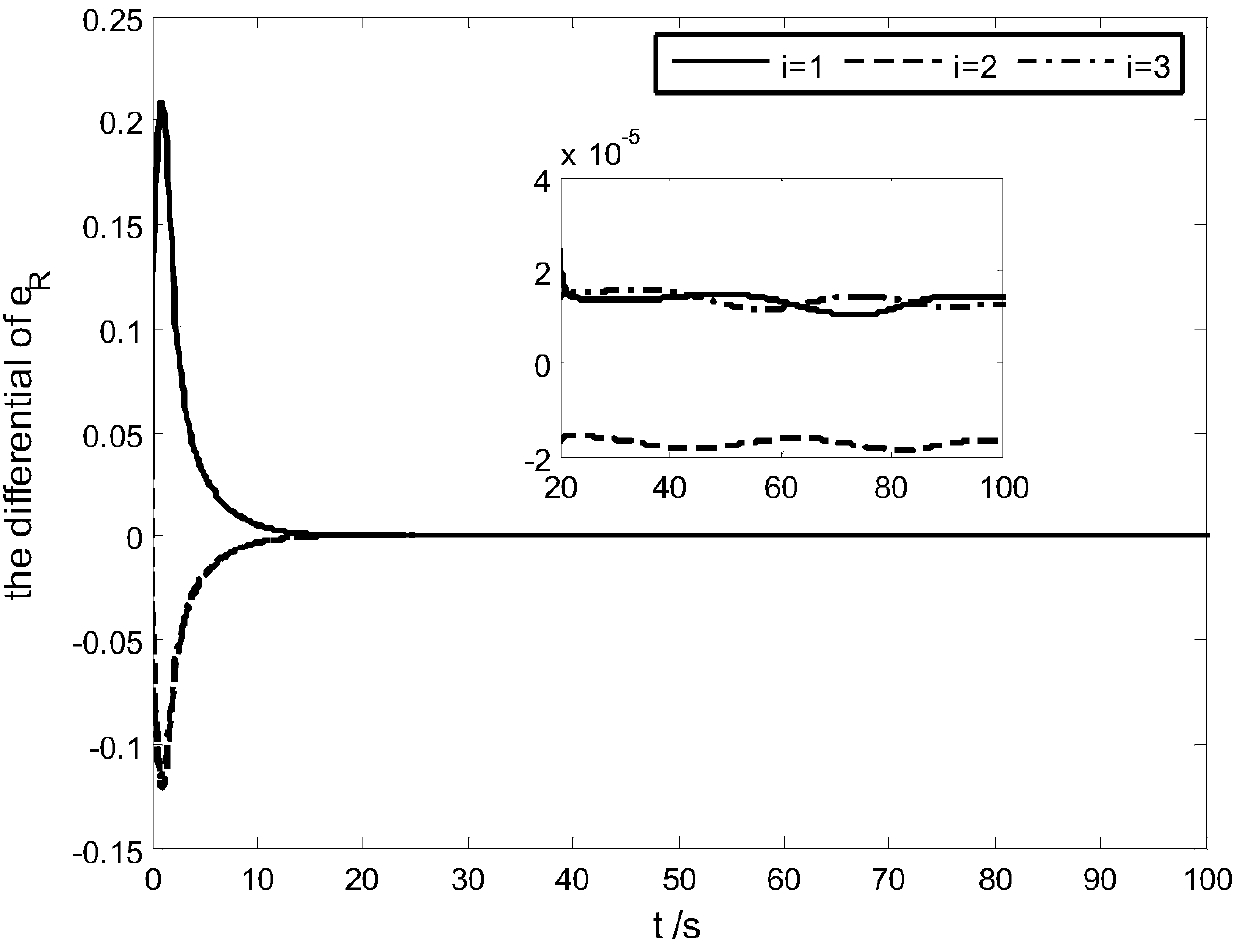
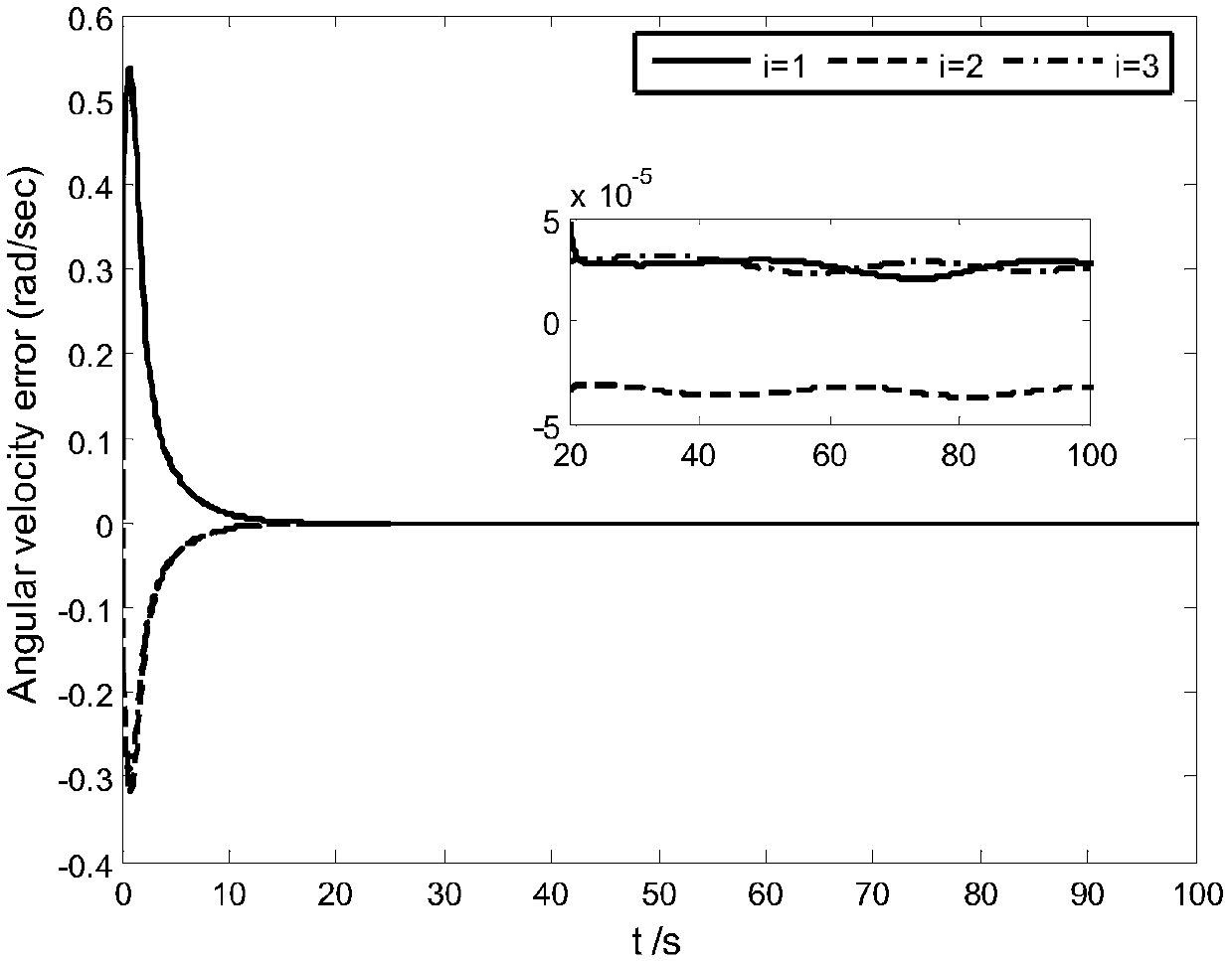
The invention relates to a sliding mode control method of an input saturated spacecraft attitude terminal, belonging to the technical field of spacecraft attitude adjustment. According to the method,two non-unwinding robust finite-time control methods are designed for a spacecraft and are a compensation known bounded method and a hyperbola tangent function and auxiliary system control method. According to the compensation known bounded method, known bounded external disturbances can be compensated, and external disturbance and input saturation problems can be solved by using the hyperbola tangent function and auxiliary system control method. The Lyapunov theorem is used to prove the finite-time stability and asymptotic stability of an entire closed-loop system. A simulation result shows that a controller can make the spacecraft to track a time-varying reference attitude signal within a limited time.

Description

technical field [0001] The invention belongs to the technical field of spacecraft attitude adjustment, and in particular relates to an input-saturated spacecraft attitude terminal sliding mode tracking control method. Background technique [0002] Attitude control of spacecraft is widely used in space missions, such as earth observation and rendezvous and docking. More and more experts and scholars have shown great interest in attitude control of spacecraft. [0003] Wen and Kreutz-Delgado proposed a general framework based on four-element analysis for rigid body attitude tracking control problems. [0004] Due to the non-uniqueness of the attitude described by the four elements of the unit, the system unwinds, which eventually leads to additional fuel consumption. When the closed-loop system approaches the desired attitude equilibrium state, unwinding allows the spacecraft to fly a significant additional distance before returning to the desired attitude. [0005] The exis...

Claims


Application Information

Patent Timeline
IPC IPC(8): G05B13/04
Inventor 李鹏周彦兰永红盘宏斌刘勇向礼丹赵昆仑
Owner XIANGTAN UNIV
Learn More