Base station array antenna and base station radio frequency equipment

A technology for array antennas and base station antennas, which is applied in the directions of antennas, antenna arrays, antenna supports/installation devices, etc., and can solve problems such as narrow frequency bands

Pending Publication Date: 2018-01-19
SUS TELECOMM +1
View PDF0 Cites 14 Cited by
  • Summary
  • Abstract
  • Description
  • Claims
  • Application Information

AI Technical Summary

Problems solved by technology

[0004] The present invention provides a base station array antenna to solve th...

Method used


Image

  • Base station array antenna and base station radio frequency equipment
  • Base station array antenna and base station radio frequency equipment
  • Base station array antenna and base station radio frequency equipment

Examples


Embodiment Construction

[0037] In order to make the technical problems, technical solutions and beneficial effects to be solved by the present invention clearer, the present invention will be further described in detail below in conjunction with the accompanying drawings and embodiments. It should be understood that the specific embodiments described here are only used to explain the present invention, not to limit the present invention.

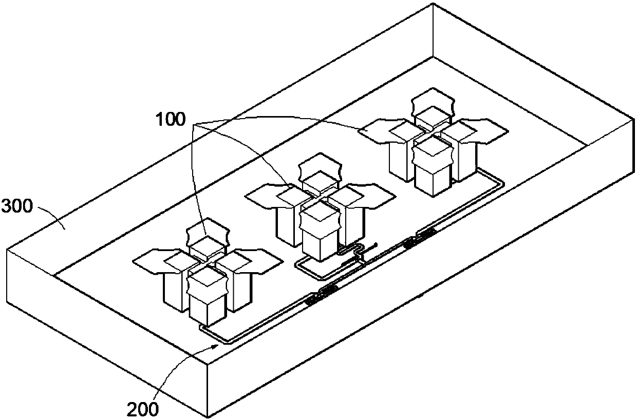
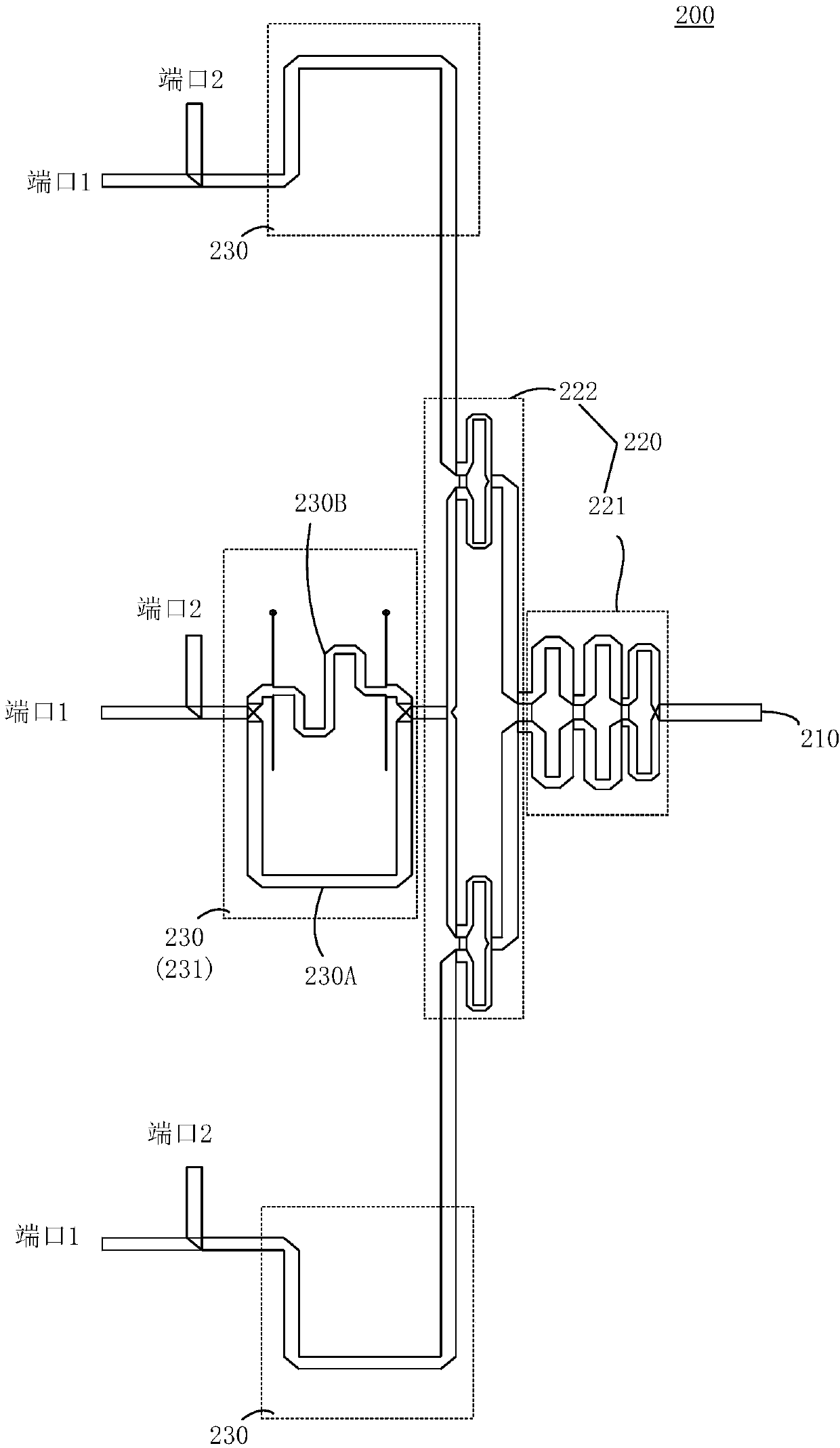
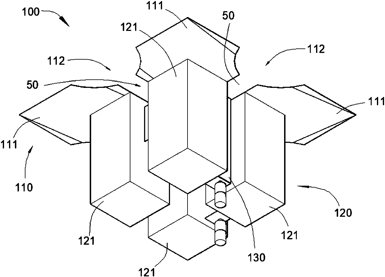
[0038] see figure 1 and figure 2 , the base station array antenna applicable to base station radio frequency equipment in a preferred embodiment of the present invention includes a plurality of array antennas 100 and a feed network 200 connected to each array antenna 100, the feed network 200 includes an input port 210, a power divider The controller unit 220 and a plurality of reconfigurable units 230. In the embodiment, three array antennas 100 are used for illustration. That is, there are three reconfigurable units 230 .

[0039] Input port 210 is used for ...


PUM


Abstract

The invention provides a base station antenna and base station radio frequency equipment. The base station antenna comprises a plurality of array antennas and a feed network connected with the array antennas, wherein the feed network comprises an input port for being connected with an external circuit, a power divider unit and a plurality of reconfigurable units, wherein an input end of the powerdivider unit is connected with the input port; the power divider unit is used for carrying out power distribution on a transmission signal to broaden a frequency band; the input ends of the reconfigurable units are connected with various output pends of the power divider unit separately; the reconfigurable units are used for carrying out phase reconfiguration on the transmission signal; and the output end of each reconfigurable unit is connected with one array antenna separately. According to the base station array antenna and the base station radio frequency equipment, power distribution is carried out on the transmission signal through a power divider, so that the impedance bandwidth is increased and broadening of the frequency band is achieved; and the transmission signal is subjected to phase reconfiguration through the reconfigurable units and then feeds the power.

Description

technical field [0001] The invention belongs to the technical field of antennas, and in particular relates to a base station array antenna and base station radio frequency equipment with reconfigurable lobe applicable to the fifth generation communication system. Background technique [0002] With the rapid development of mobile communication systems, there is an increasing demand for base station antennas with wide lobes and wide frequency bands. In order to meet the requirements of lobes and frequency bands in practical applications, such as wider and wider coverage, in recent years, people are studying different types of linearly polarized antennas. [0003] At present, there are wide-band unidirectional multi-polarized antennas with stable wide lobes on the H-plane, but the lobe width of the H-plane is only 63.3° in the entire application frequency band. While the other can achieve a frequency bandwidth as high as 41%, while the electromagnetic dipole antenna with a wid...

Claims


Application Information

Patent Timeline
IPC IPC(8): H01Q1/24H01Q1/36H01Q1/50H01Q21/00H01Q25/00
Inventor 冯波涛涂雅婷
Owner SUS TELECOMM
Why Eureka
Try Eureka