Power distribution box capable of removing moisture

A distribution box, moisture technology, applied in the substation/distribution device shell, electrical components, substation/switch layout details, etc., can solve the problem that the dehumidification effect is not obvious, the air in the distribution box cannot be circulated, and cannot be dehumidified, etc. problem, to achieve the effect of improving the dehumidification effect

Inactive Publication Date: 2018-01-19
林淑妹
View PDF4 Cites 9 Cited by
  • Summary
  • Abstract
  • Description
  • Claims
  • Application Information

AI Technical Summary

Problems solved by technology

[0005] Aiming at the deficiencies in the prior art, the purpose of the present invention is to provide a distribution box capable of dehumidification, so as to solve the problem that the existing distribution box is equipped with a dehumidifier to remove the moisture in the box, and cannot perform a more comprehensive dehumidification of the box. Dehumidification, the dehumidification effect is not obvious, and the air in the distribution box cannot be circulated

Method used


Image

  • Power distribution box capable of removing moisture
  • Power distribution box capable of removing moisture
  • Power distribution box capable of removing moisture

Examples


Embodiment 1

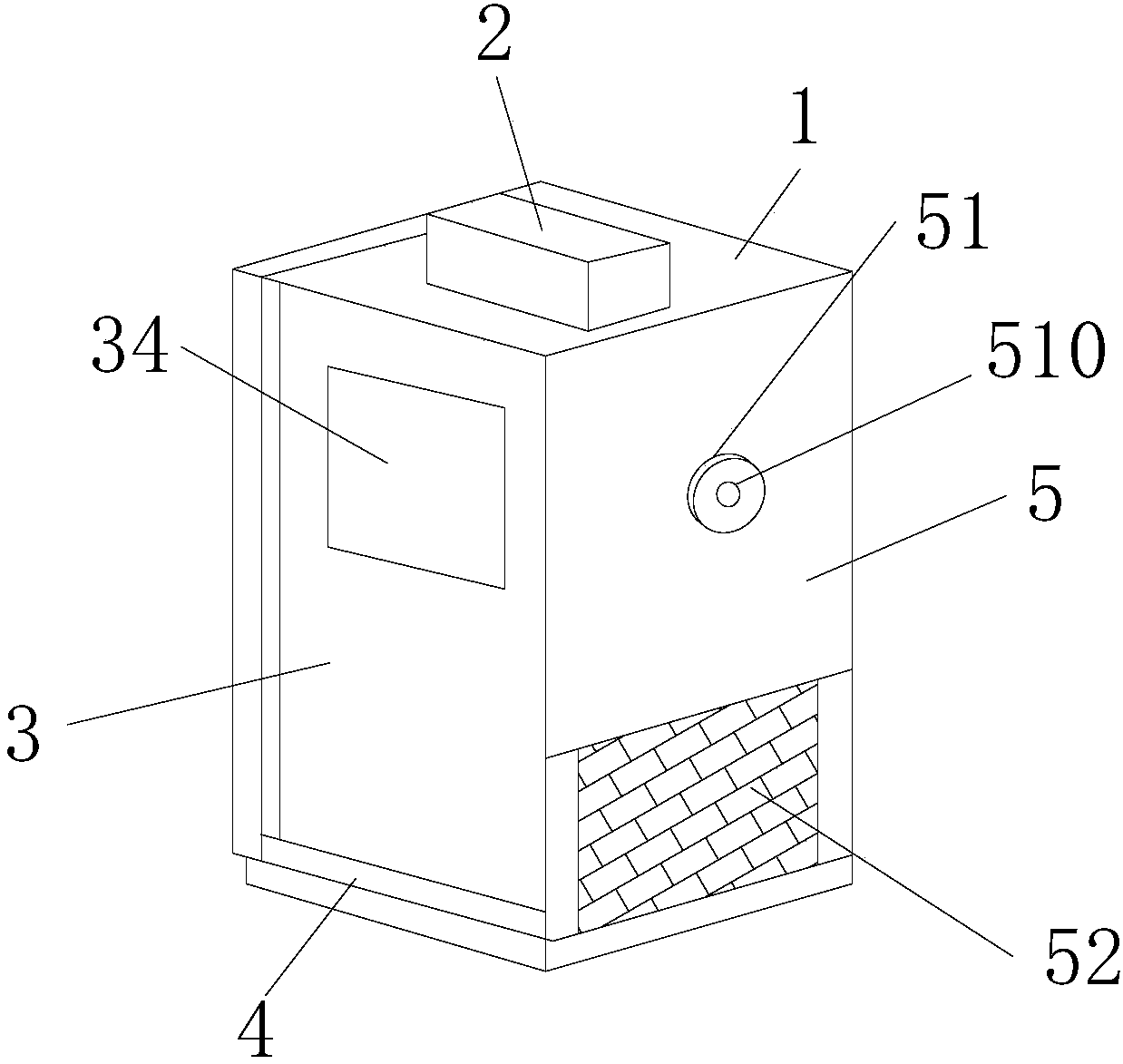
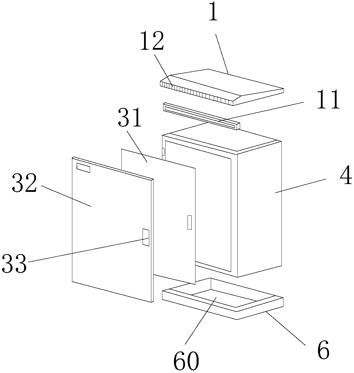
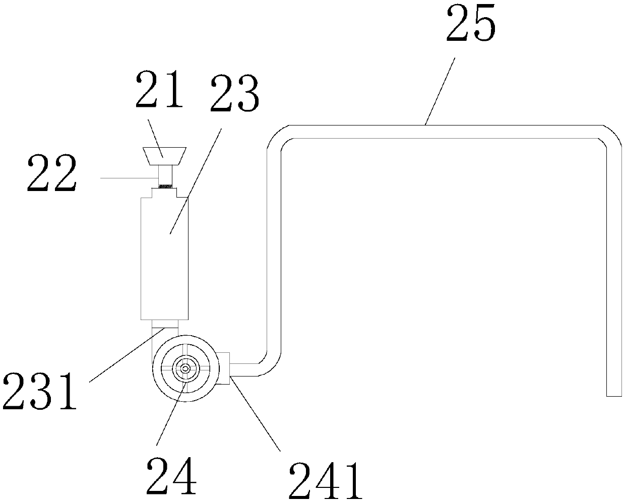
[0032] see Figure 1 to Figure 12, the present invention provides a dehumidifying power distribution box, the structure of which comprises a top plate 1, a tubular ventilation and dehumidification structure 2, a box door 3, a power distribution box body 4, a side plate 5, and a base 6. The power distribution box The top of the body 4 is movably connected with the top plate 1, the side plate 5 and the distribution box body 4 are parallel to each other, the top plate 1 is provided with a sliding track 11 and an air vent 12, and one side of the top plate 1 is connected to the distribution box through the sliding track 11. The electric box body 4 is connected, the vent 12 is embedded in the top plate 1, and a tubular ventilation and dehumidification structure 2 is fixed above the top plate 1, and the side end of the distribution box body 4 and the side plate 5 are an integrated structure , the side plate 5 is provided with a lead cover 51, the lead cover 51 is fixedly connected to...


PUM


Abstract

The present invention discloses a power distribution box capable of removing the moisture. The power distribution box structurally comprises a top plate, a pipe type ventilating and dehumidifying structure, a box door, a power distribution box body, a side plate and a base. The top of the power distribution box body is movably connected with the top plate. The side plate and the power distributionbox body are parallel to each other. The top plate is provided with a sliding rail and a ventilation opening. One side of the top plate is connected with the power distribution box body through the sliding rail. The ventilation opening is embedded in the top plate. The pipe type ventilating and dehumidifying structure is fixedly arranged on the top plate. The side end of the power distribution box body and the side plate are of an integrated structure. The side plate is provided with a lead cover. The lead cover is fixedly connected with the side plate. According to the invention, the pipe type ventilating and dehumidifying structure is fixedly arranged on the top plate. Therefore, the hot air is filtered firstly and then is fed into the power distribution box, so that dusts are preventedfrom entering the power distribution box to influence the normal operation of various components. Simultaneously, a plurality of rotating wind spraying heads are arranged. As a result, the hot air issprayed from multiple angles to realize the dehumidifying function in the power distribution box more comprehensively. The dehumidifying effect is greatly improved, so that the circulation of the airflow in the power distribution box is realized.

Description

technical field [0001] The invention relates to a distribution box capable of dehumidification, which belongs to the technical field of distribution boxes capable of dehumidification. Background technique [0002] The arrival of the rainy season is a huge test for the dehumidification work of the power distribution room. In recent years, there have been more and more news about the power distribution room being damp, and many places and communities have experienced power outages due to the damp of the power distribution room. Especially in many power distribution rooms built in the basement, dehumidification is my problem. There are also many keywords about moisture-proof and dehumidification of power distribution rooms on the Internet, which shows the importance of dehumidification in power distribution rooms. [0003] The power distribution cabinet must first be waterproofed, and the holes are all plugged with fireproof mud, which is relatively good for sealing. Modern in...

Claims


Application Information

Patent Timeline
IPC IPC(8): H02B1/28H02B1/46H02B1/54
Inventor 林淑妹王晨莉孙立江
Owner 林淑妹
Why Eureka
Try Eureka