
Drawer structure of switch cabinet

A switchgear and drawer technology, applied in pull-out switchgear, switchgear, switchgear components, etc., can solve problems such as hidden dangers, existing safety, and shortening the service life of equipment

Active Publication Date: 2019-10-08
ZHEJIANG SHENGZHONGYI ELECTRIC POWER TECH
View PDF4 Cites 0 Cited by
  • Summary
  • Abstract
  • Description
  • Claims
  • Application Information

AI Technical Summary

Problems solved by technology

[0003] The drawer structure usually includes a drawer body, an operating component and a control component. The control component includes a main circuit and a detection circuit. The operating component includes a contact push plate that can communicate with the main circuit and a contact push block that can communicate with the detection circuit. In the technology, both the contact push plate and the contact push block are fixedly connected to the drawer body, the contact push plate is used to realize the conduction of the main circuit, the contact push block is used to realize the conduction of the detection circuit, and the operating components and There are three position coordination relationships between the control components, which are the separation position, the test position and the connection position. The separation position is that the contact push plate is disconnected from the main circuit, and the contact push block is disconnected from the detection circuit, that is, it does not work at all. The position of the drawer can be opened for maintenance and other operations to avoid danger. The test position is that the contact push plate is disconnected from the main circuit, the contact push block is connected to the detection circuit, and only the detection circuit is connected, which can be used as a test. , also known as the test state, the connection position is that the contact push plate is connected to the main circuit, the contact push block is disconnected from the detection circuit, the main circuit is in a state that can be fully connected to work, and it can work normally after closing, also known as In the connected position, the existing technology realizes the change of three positions by moving the drawer body, especially in the separation position and the test position, the drawer body is in a fully opened or half-open state, which makes there is a safety hazard during use. At the same time, the overall protection level is not high, and it is easy for dust or other impurities to enter the drawer cabinet, reducing the service life of the equipment

Method used


Image

  • Drawer structure of switch cabinet
  • Drawer structure of switch cabinet
  • Drawer structure of switch cabinet

Examples


Embodiment Construction

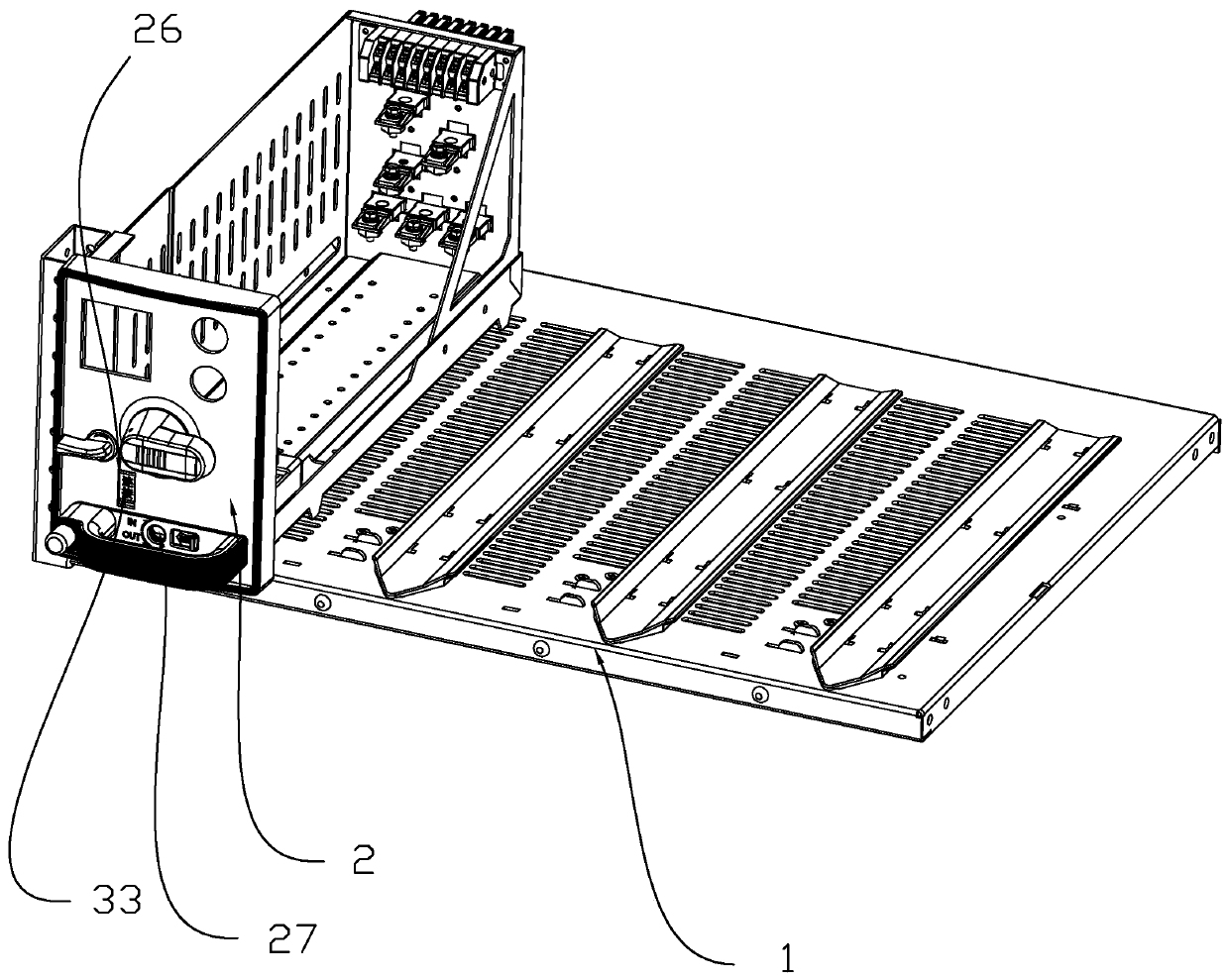
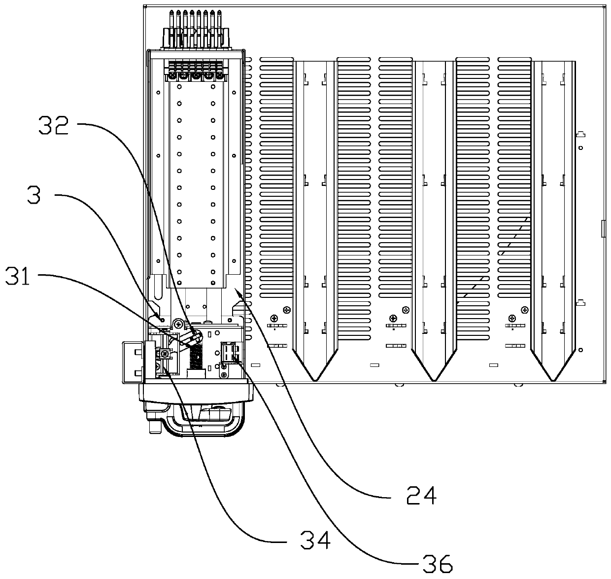
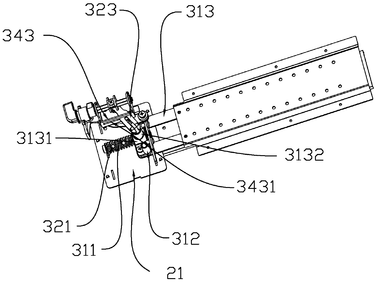
[0039] Specific embodiments of the present invention such as Figure 1-13As shown, a drawer structure of a switchgear includes a cabinet body 1 and a drawer body 2 arranged in the cabinet body 1. An operating assembly 3 is arranged in the drawer body 2. The operating assembly 3 includes a pushing mechanism 31 and a locking mechanism 32. And the display mechanism 33, the propulsion mechanism 31 includes the rotating screw rod 311, the contact push block 312 and the threaded contact push plate 313 arranged in the drawer body 2, the contact push block 312 and the contact push plate 313 are fixed or integrated Set, the rotating screw rod 311 is rotated and arranged in the drawer body 2, the rotating screw rod 311 is threaded with the contact push plate 313, the rotating screw rod 311 rotates to drive the contact push plate 313 and the contact push block 312 to move, and the drawer body 2 is provided with a The handle that drives the rotating screw 311 to rotate. The locking mechan...


PUM


Abstract

A drawer structure of a switch cabinet, comprising a cabinet body (1) and a drawer body (2) provided in the cabinet body. An operation assembly (3) is provided in the drawer body; the operation assembly comprises a feed mechanism (31), a locking mechanism (32), and a display mechanism (33); the feed mechanism comprises a rotating screw (311), a contact pushing block (312), and a contact pushing plate (313) with a screw thread provided in the drawer body; the contact pushing block and the contact pushing plate are fixedly or integrally provided; the rotating screw is rotatably provided in the drawer body; the rotating screw and the contact pushing plate are provided together by means of the screw threads; the rotating screw rotates to drive the contact pushing plate and the contact pushing block to move; a handle for driving the rotating screw to rotate is provided on the drawer body; the locking mechanism comprises locking holes formed on the outer peripheral surface of the rotating screw and a locking rod capable of being in insertion limiting fit with the locking hole; the locking holes are formed at intervals along the axial direction of the rotating screw; the locking rod is linked with the contact pushing plate; and when the locking rod moves to be aligned with a locking hole, the locking rod and the locking hole form insertion fit.

Description

technical field [0001] The invention relates to a switch cabinet, in particular to a drawer structure of the switch cabinet. Background technique [0002] At present, the switchgear is a kind of electrical equipment, and its main function is to open and close, control and protect electrical equipment during the process of power generation, transmission, distribution and power conversion in the power system. Drawers of various sizes and models are set on the switch cabinet, and different circuit controllers are set in each drawer, so that the circuit is generally controlled through the switch cabinet. [0003] The drawer structure usually includes a drawer body, an operating component and a control component. The control component includes a main circuit and a detection circuit. The operating component includes a contact push plate that can communicate with the main circuit and a contact push block that can communicate with the detection circuit. In the technology, both the ...

Claims


Application Information

Patent Timeline
Patent Type & Authority Patents(China)
IPC IPC(8): H02B11/133H02B11/04
Inventor 潘正东潘琦朱明辉钟杰王毅
Owner ZHEJIANG SHENGZHONGYI ELECTRIC POWER TECH
Learn More