Two-way wireless-energy stable transmission system circuit topology applicable to wide-coupling coefficient variation range and control strategy
A two-way radio and coupling coefficient technology, applied in the direction of circuit devices, electrical components, etc., can solve the problems of small effective range and poor anti-displacement ability of the wireless power transmission system, and achieve the improvement of design ideas and control methods, stable wireless power transmission, Achieve the effect of wireless power transmission
- Summary
- Abstract
- Description
- Claims
- Application Information
AI Technical Summary
Problems solved by technology
Method used
Image

Examples
Embodiment 1
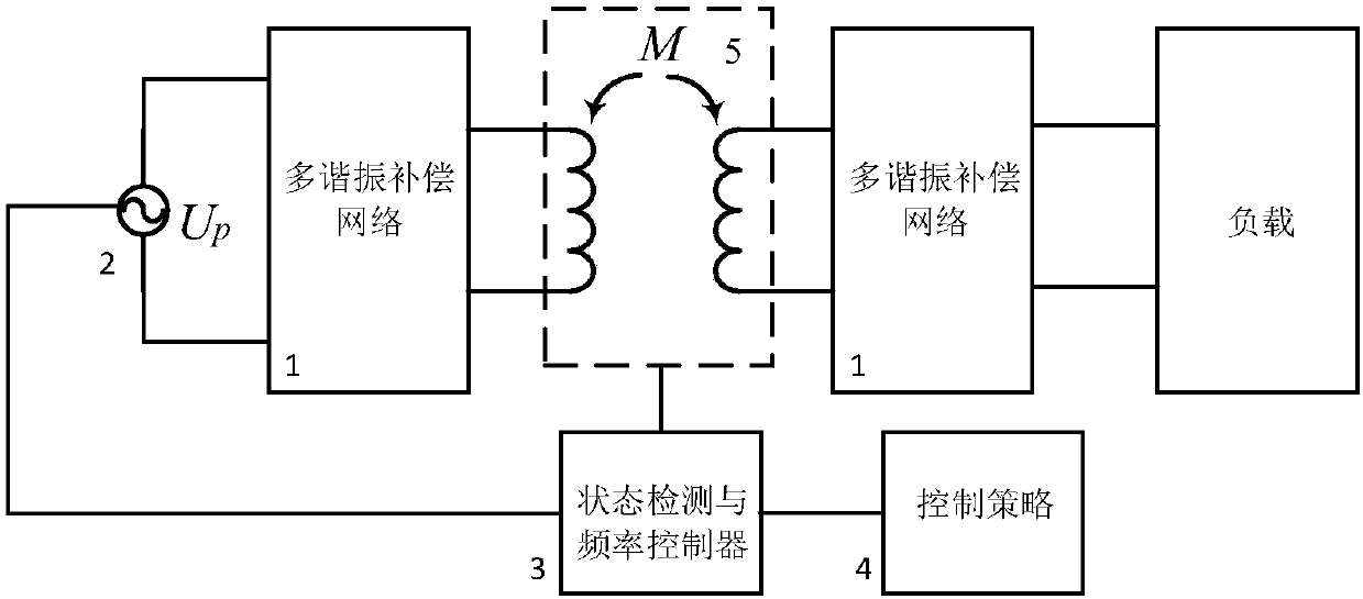
[0041] A two-way wireless power stable transmission system circuit suitable for wide coupling coefficient variation range, such as figure 2As shown, the power transmission system circuit includes two multi-resonance structures 1, a variable frequency power supply 2, a state detection and frequency controller 3, a frequency conversion control strategy module 4, a coupling mechanism 5 and an alarm device; one of the multi-resonance structures 1 is provided in The primary winding end of the coupling mechanism 5, and the two power supply ends of the multi-resonance structure 1 are connected to the two power supply ends of the variable frequency power supply 2; the other multi-resonance structure 1 is arranged on the secondary winding of the coupling mechanism 5. The frequency control signal output end of the state detection and frequency controller 3 is connected with the frequency control signal input end of the variable frequency power supply 2; the coupling state detection end ...
Embodiment 2
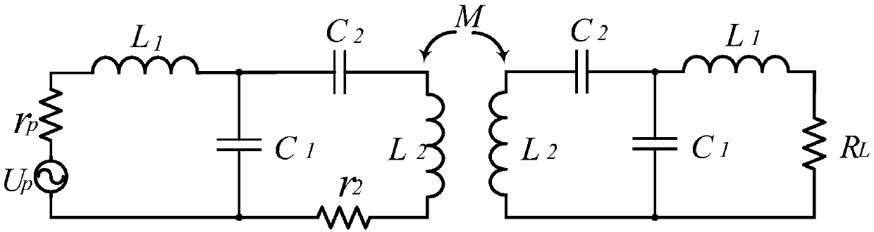
[0043] Embodiment 2 is a further limitation to the circuit of the two-way wireless power stable transmission system described in Embodiment 1 that is suitable for a wide variation range of coupling coefficients. The multi-resonance structure 1 in the power transmission system circuit adopts a bilateral LCC compensation network structure. specific:
[0044] A power transmission system circuit based on a bilateral LCC compensation network structure includes a variable frequency power supply U P , two resonant inductance elements L 1 , two resonant capacitive elements C 1 , two resonant capacitive elements C 2 , the primary winding L of the coupling mechanism 2 , the secondary winding L of the coupling mechanism 2 , resistance r 2 and load R L , state detection and frequency controller 3 and variable frequency variable frequency control strategy module 4; the primary winding L of the coupling mechanism 2 A resonant capacitive element C is connected in series at both ends o...
Embodiment 3
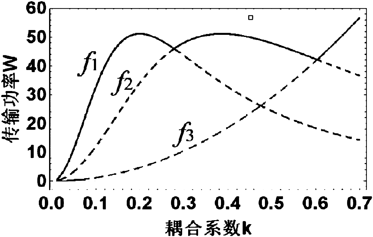
[0057] Embodiment 3 is a further limitation of the circuit of the two-way wireless power stable transmission system described in Embodiment 1 that is suitable for a wide coupling coefficient variation range. The frequency conversion control strategy 4 in the power transmission system circuit can be implemented by the following methods. The first strategy is to generate a swept frequency signal through the signal source. The first strategy is the frequency sweep judgment under the condition of unknown parameters. Figure 4 As shown, for a multi-resonance system, after placing the charging device, the frequency corresponding to the maximum output power in this state is determined by detecting the output power at different resonance frequencies, and this frequency can be used for wireless power transmission at this time. The second strategy is based on Figure 5 What is shown is the measurement judgment under the premise of calibrating the range of the coupling coefficient. For ...
PUM
 Abstract
Description
Claims
Application Information