Compressor housing for supercharger

A technology of compressor housing and supercharger, which is applied to machines/engines, components of pumping devices for elastic fluids, mechanical equipment, etc., can solve problems such as impeller damage, achieve simple structure, reduce cost, and structure simple effect

Inactive Publication Date: 2018-01-19
株式会社欧德克斯 +1
View PDF4 Cites 1 Cited by
  • Summary
  • Abstract
  • Description
  • Claims
  • Application Information

AI Technical Summary

Problems solved by technology

[0004] However, if the clearance is reduced, the impeller may be damaged if, for example, the blades of the impeller come into contact with the shroud surface of the compressor housing due to vibration, vibration of the impeller rotating shaft, etc.

Method used


Image

  • Compressor housing for supercharger
  • Compressor housing for supercharger
  • Compressor housing for supercharger

Examples


Embodiment 1

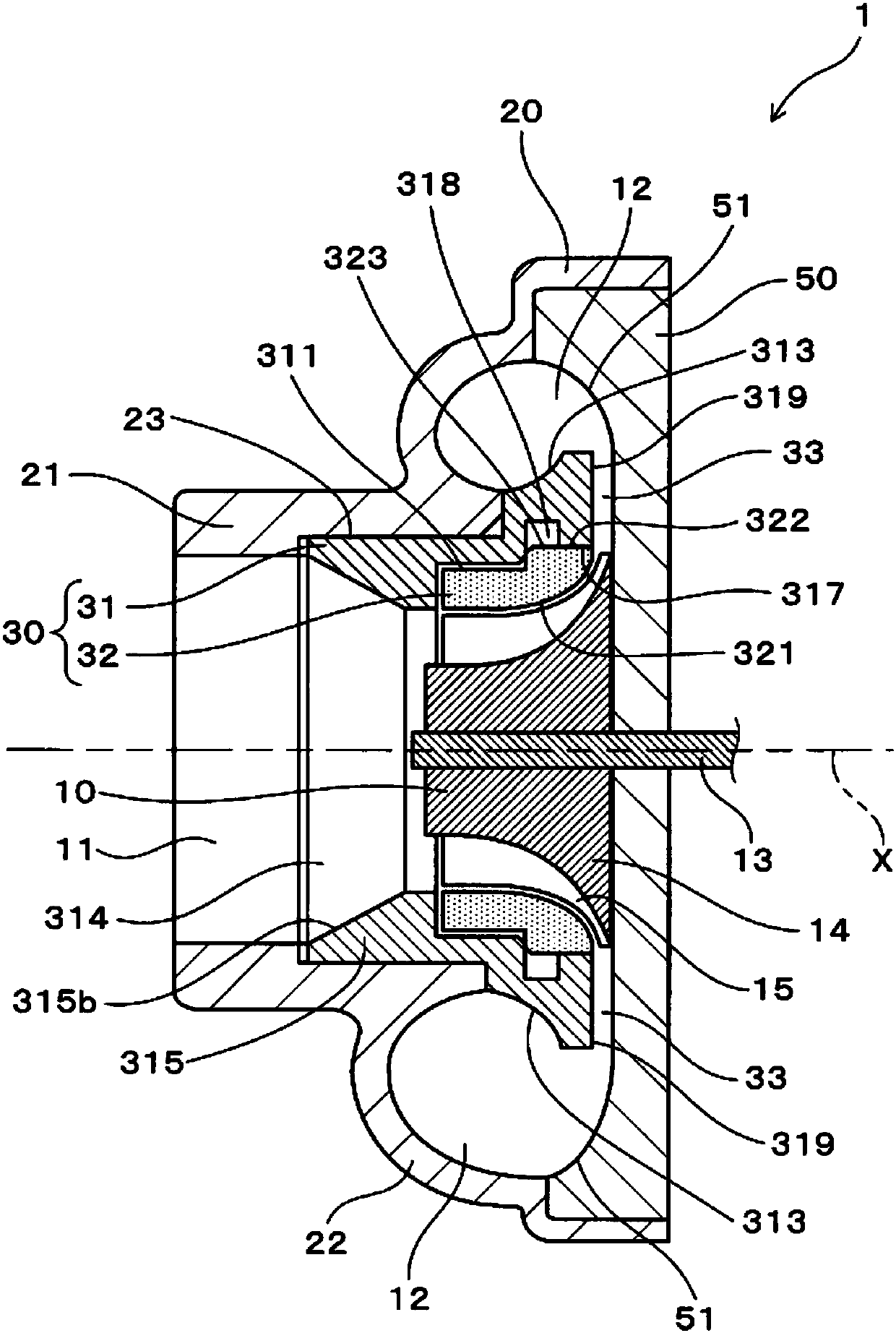
[0061] use Figure 1 to Figure 5 The compressor casing for the supercharger of this example will be described.

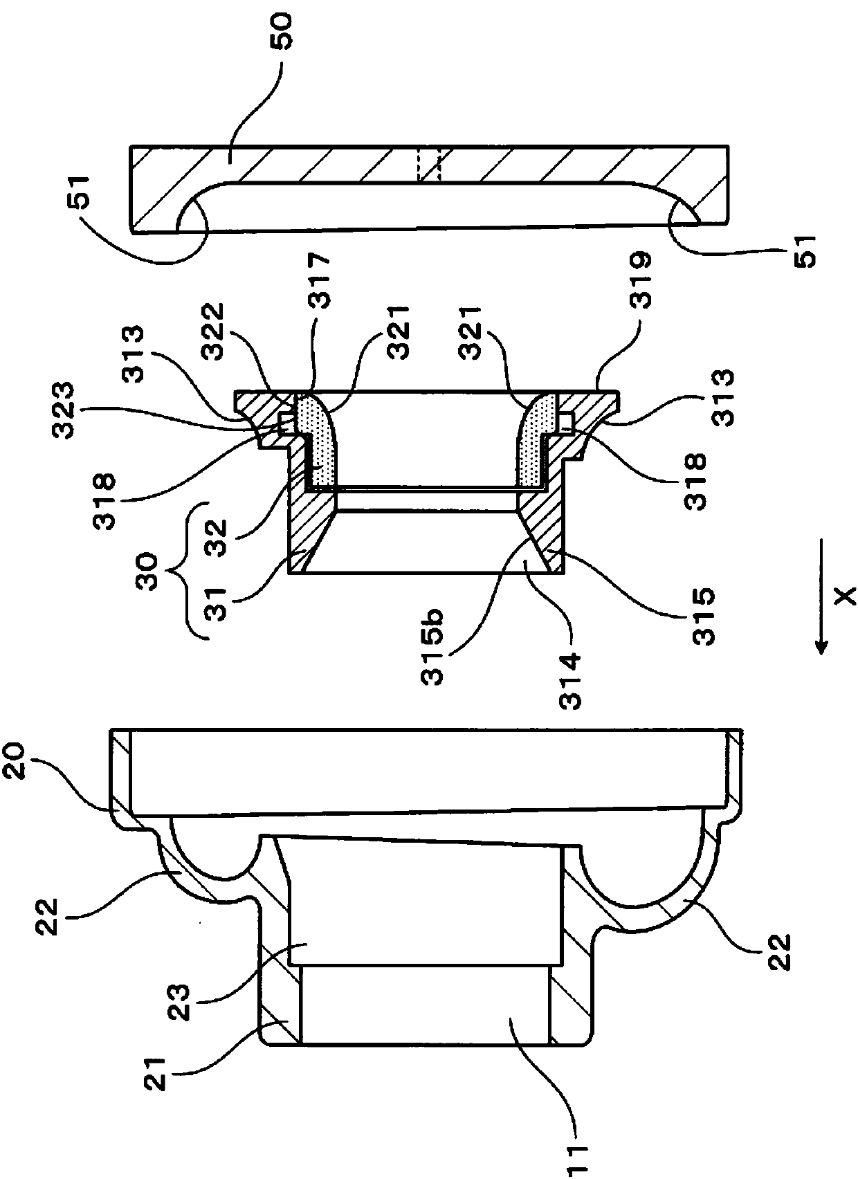
[0062] like figure 1 As shown, a compressor housing 1 for a supercharger (hereinafter, also referred to as “compressor housing 1 ”) of this example is configured to accommodate an impeller 10 and includes a scroll portion 20 and a shroud portion 30 .

[0063] The scroll portion 20 has: an air inlet 11 through which air is sucked toward the impeller 10; To the vortex chamber 12.

[0064] like figure 2 As shown, the shield portion 30 includes: an elastically deformable annular sliding member 32 whose inner peripheral surface 321 forms a shield surface 321 ; and an annular sliding member fixing portion 31 for fixing the sliding member 32 .

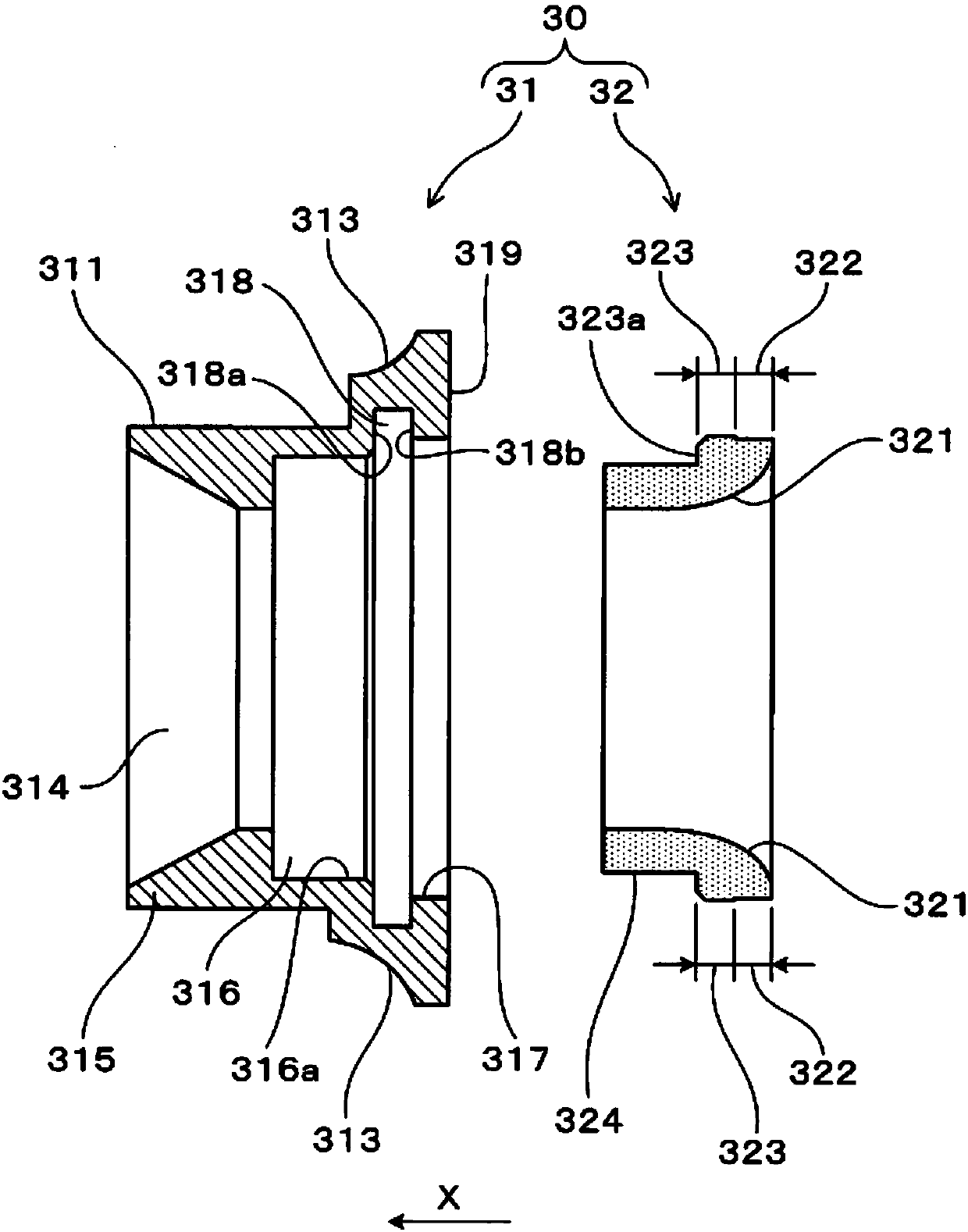
[0065] like image 3 As shown, the slide member fixing part 31 has: a press-fit recess 317 into which the slide member 32 is press-fit; The manner of depression is formed along the circumferential direction.

[0066] The sl...

Embodiment 2

[0107] In the compressor casing 1 that the supercharger of this example is used, as Figure 7 As shown, the sliding member 32 does not have a cylindrical portion 324 ( Figure 4 ), for the wall surface 318a on the front side in the press-in direction X of the groove portion 318, the end portion 323a on the front side in the press-in direction X of the slide member 32 and the front side in the press-in direction X of the groove portion 318 of the slide member fixing portion 31 The wall surface 318a abuts against. Thereby, the slide member 32 is positioned in the axial direction X at the end portion 323a on the front side in the press-fitting direction X. As shown in FIG. In addition, the same code|symbol is attached|subjected to the structural element equivalent to Example 1, and the description is abbreviate|omitted.

[0108] According to this example, in addition to the function and effect achieved by providing the cylindrical portion 324 on the front side in the press-fit ...

Embodiment 3

[0110] In the compressor casing 1 that the supercharger of this example is used, as Figure 8 As shown, the slide member 32 has a notch 325 formed at the rear end of the bulge 323 in the press-fit direction X (ie, the boundary between the bulge 323 and the press-fit abutting portion 322 ). like Figure 8 As shown, the notch portion 325 is formed in the circumferential direction along the wall surface 318 b on the rear side in the press-fitting direction X of the groove portion 318 . The notch portion 325 is a groove having a V-shaped cross-sectional shape in the axial direction X, and is formed uniformly over the entire circumferential direction. In addition to the V-shape, the cross-sectional shape of the notch portion 325 may be U-shaped, rectangular, arc-shaped, or the like. In addition, the same code|symbol is attached|subjected to the structural element equivalent to Example 1, and the description is abbreviate|omitted.

[0111] The depth of the notch 325 (from the sur...


PUM


Abstract

This invention addresses the problem of providing a compressor housing for a supercharger, which is simple in configuration and with which it is possible to reliably secure a sliding member. To solvethis problem, a compressor housing (1) for a supercharger is provided with a scroll part (20) having a scroll chamber, and a shroud part (30) having a shroud surface (321). The shroud part (30) comprises an annular sliding member (32) which forms the shroud surface (321), and an annular sliding member securing part (31). The sliding member securing part (31) has a press-fitting concavity (317) into which the sliding member (32) is press-fitted, and a groove part (318) formed in the circumferential direction as being recessed diametrically outward in the front side of the sliding member (32) inthe press-fitting direction (X). The sliding member (32) has a press-fitting contact part (322) which comes into contact with the inner peripheral surface of the press-fitting concavity (317), and abulging part (323) which bulges into the groove part (318) in a position of facing the groove part (318).

Description

technical field [0001] This invention relates to compressor housings for superchargers. Background technique [0002] A compressor (compressor) used for a supercharger such as a turbocharger of an automobile has a compressor housing configured to accommodate an impeller, and is provided with an air inlet through which air is directed toward The impeller sucks in; a swirl chamber formed in a circumferential direction on the outer peripheral side of the impeller, into which air discharged from the impeller is introduced; and a shroud surface opposed to the impeller. [0003] In the compressor configured as described above, the compression efficiency of the compressor can be improved by reducing the gap between the blades of the impeller and the shroud surface of the compressor housing as much as possible. [0004] However, if the gap is reduced, the impeller may be damaged if, for example, the blades of the impeller come into contact with the shroud surface of the compressor ...

Claims


Application Information

Patent Timeline
Patent Type & Authority Applications(China)
IPC IPC(8): F02B39/00F02C7/00F04D29/42F04D29/62
CPCF01D11/122F04D29/162F04D29/4206F05D2220/40F05D2260/37F02C7/00F04D29/62F02C6/12F04D29/4213F04D29/624
Inventor 三好智己矶谷知之米泽幸一
Owner 株式会社欧德克斯
Why Eureka
Try Eureka