High-efficiency coating stirring and mixing machine

A technology of stirring and mixing and stirring mechanism, which is applied in the direction of mixers with rotating stirring devices, mixers, mixer accessories, etc., can solve the problems of simultaneous mixing of difficult materials, difficult mixing of materials uniformly, low mixing efficiency, etc., and achieve improvement Stirring efficiency, convenient pick-and-place process, and the effect of improving efficiency

Inactive Publication Date: 2018-01-23
重庆彩润建材有限公司
View PDF4 Cites 20 Cited by
  • Summary
  • Abstract
  • Description
  • Claims
  • Application Information

AI Technical Summary

Problems solved by technology

[0003] The existing mixer generally installs a stirring rod directly on the top or bottom of the mixing tank, and mixes and stirs through the stirring rod. When there are many materials in the mixing tank during the mixing process, the materials in the upper part of the mixing tank are mixed evenly. Stirring time needs to

Method used


Image

  • High-efficiency coating stirring and mixing machine
  • High-efficiency coating stirring and mixing machine
  • High-efficiency coating stirring and mixing machine

Examples


Embodiment Construction

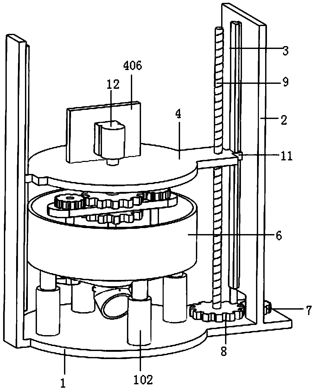
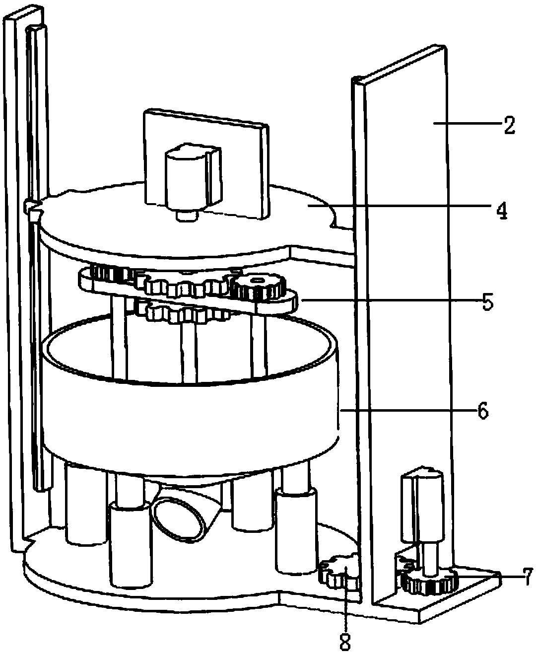
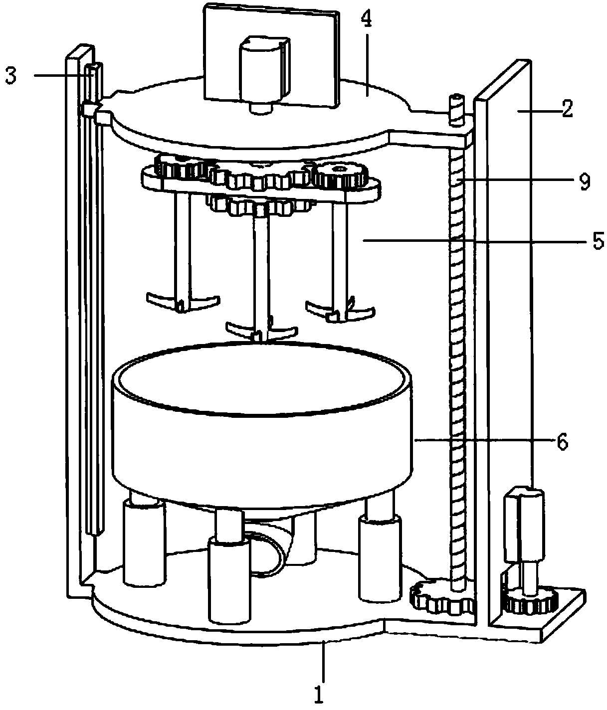
[0035] A high-efficiency paint mixing mixer, such as figure 1 , figure 2 with image 3 As shown, the fixed base 1 is included, and the two ends of the surface of the fixed base 1 are vertically fixed with two opposite positioning guide plates 2, and the inner surfaces of the two positioning guide plates 2 are relatively fixed with two opposite slide rails 3. A slide rail 3 is installed and fixed with a sliding support seat 4, and the lower end of the sliding support seat 4 is vertically fixed with a stirring mechanism 5;

[0036] A stirring tank 6 is installed and fixed on the surface of the fixing seat 1, and the stirring tank 6 is located directly below the stirring mechanism 5;

[0037] Such as Figure 4 with Figure 5 As shown, the first gear 7 and the second gear 8 are fixed on the fixed seat 1, the first gear 7 and the second gear 8 mesh, the second gear 8 is fixed with a lead screw 9, and the lead screw 9 passes through the sliding support The seat 4 drives the sc...


PUM


Abstract

The invention discloses a high-efficiency coating stirring and mixing machine. The high-efficiency coating stirring and mixing machine comprises a fixed base, wherein two corresponding locating guideplates are vertically and fixedly arranged at both ends of the surface of the fixed base; two corresponding slide rails are fixedly arranged at the inside surfaces of the two locating guide plates; aslide support base is fixedly arranged on the two slide rails, and a stirring mechanism is vertically and fixedly arranged at the lower end of the slide support base; a stirring tank is fixedly arranged at the surface of the fixed base, a first gear and a second gear are fixedly arranged on the fixed base, and are engaged together, a screw rod is fixedly arranged on the second gear and penetratesthrough the slide support base, and the screw rod drives the slide support base to move up and down along the slide rails in the vertical direction. The high-efficiency coating stirring and mixing machine has the advantages that by arranging the stirring mechanism, stirring rods are respectively arranged in the middle part and both sides of the stirring mechanism, and the stirring rods at the twosides can rotate around the center, and can also rotate around the self axis, so that the stirring efficiency is improved; the materials in the middle part and both sides of the stirring tank can be simultaneously mixed, so that the materials can be more uniformly mixed.

Description

technical field [0001] The field of condiment preparation of the present invention relates to a high-efficiency paint stirring mixer. Background technique [0002] The high-speed mixer is mainly aimed at pulverizing, dispersing, emulsifying, and mixing liquid raw materials with different viscosities. Through the high-speed operation of the upper and lower teeth of the dispersion plate, it is a new type of high-efficiency mixing equipment that performs high-speed and strong shearing, impacting, crushing, and crushing of the materials. Dispersion, to achieve the functions of rapid mixing, dissolving, dispersing and refining. It is an efficient equipment for stirring, dispersing and dissolving solids such as coatings. [0003] The existing mixer generally installs a stirring rod directly on the top or bottom of the mixing tank, and mixes and stirs through the stirring rod. When there are many materials in the mixing tank during the mixing process, the materials in the upper par...

Claims


Application Information

Patent Timeline
IPC IPC(8): B01F7/16B01F7/30B01F15/00
Inventor 任磊
Owner 重庆彩润建材有限公司
Why Eureka
Try Eureka