Swarf cleaning device applied to stamping die

A technology for stamping dies and cleaning devices, applied in the directions of cleaning methods and utensils, removing smoke and dust, chemical instruments and methods, etc., can solve the problems of die wear, affecting the blanking quality of workpieces, etc., and achieve the effect of simple structure

Inactive Publication Date: 2018-01-23
DONGGUAN LIANZHOU INTPROP OPERATION MANAGEMENT CO LTD
View PDF9 Cites 14 Cited by
  • Summary
  • Abstract
  • Description
  • Claims
  • Application Information

AI Technical Summary

Problems solved by technology

[0002] Stamping is a common manufacturing method in mechanical processing at present. Its stamping generally consists of an upper mold and a lower mold. At the same time, some upper molds are also equipped with a punch. Chips are generated, and the accumulation of chips will affect the punching quality of subsequent workpieces and the wear of the die

Method used


Image

  • Swarf cleaning device applied to stamping die

Examples


Embodiment

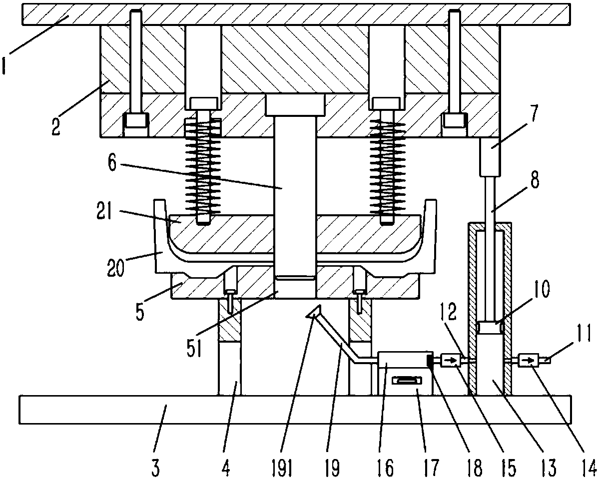
[0014] Example: see figure 1 As shown, a chip cleaning device applied to stamping dies includes an upper die mounting plate 1 and an upper die 2, the upper die 2 is fixed on the lower end surface of the upper die mounting plate 1, and the lower side of the upper die 2 is provided with a lower The mold 5 and the lower mold 5 are fixed on the column 4, the lower end of the column 4 is fixed on the lower mold mounting plate 3, the upper mold 2 is equipped with a lower die 21, and the lower die 21 is inserted with a punch 6, and the punch 6 The upper end of the upper die is fixed on the upper die 2, the lower die 5 is formed with a punching hole 51 opposite to the punch 6, a fixed block 7 is fixed on the side of the upper die 2, and a vertical piston rod 8 is fixed on the fixed block 7. , the lower end of the piston rod 8 is fixed with a piston 10, the piston 10 is inserted in the cylinder 13, the lower end of the cylinder 13 is fixed on the lower mold mounting plate 3, and the lo...


PUM


Abstract

The invention discloses a swarf cleaning device applied to a stamping die. The swarf cleaning device comprises an upper die mounting plate and an upper die, the upper die is fixed on the lower end face of the upper die mounting plate, a lower die is arranged on the lower side of the upper die and fixed on stand columns, and the lower ends of the stand columns are fixed on a lower die mounting plate. A lower pressing die is arranged on the upper die and is in inserted connection with a punch, the upper end of the punch is fixed on the upper die, and a punched hole opposite to the punch is formed in the lower die. A fixed block is fixed at one side edge of the upper die, a vertical piston rod is fixed on the fixed block, a piston is fixed at the lower end of the piston rod and inserted intoan air cylinder, the lower end of the air cylinder is fixed on the lower die mounting plate, an exhaust pipe and an air suction pipe are fixed at the lower end of the air cylinder, and the air suctionpipe is fixedly connected with a swarf collection box. A dust absorption pipe is fixed on the side, back on to the air suction pipe, of the swarf collection box. The front end of the dust absorptionpipe is bent to form an inclined pipe. The swarf cleaning device can absorb swarf produced by cutting on the die, thereby reducing die abrasion and guaranteeing the blanking quality of subsequent workpieces.

Description

Technical field: [0001] The invention relates to the technical field of molds, and more specifically relates to a chip cleaning device applied to stamping molds. Background technique: [0002] Stamping is a common manufacturing method in mechanical processing at present. Its stamping generally consists of an upper mold and a lower mold. At the same time, some upper molds are also equipped with a punch. Chips are generated, and the accumulation of chips will affect the blanking quality of subsequent workpieces and the wear of the die. Invention content: [0003] The object of the present invention is to address the deficiencies of the prior art, and to provide a chip cleaning device applied to a stamping die, which can effectively remove the chips generated during the punching process of the die. [0004] To achieve the above object, the technical scheme adopted in the present invention is as follows: [0005] A chip cleaning device applied to a stamping die, comprising a...

Claims


Application Information

Patent Timeline
Patent Type & Authority Applications(China)
IPC IPC(8): B21D28/14B08B15/04
Inventor 杨勇
Owner DONGGUAN LIANZHOU INTPROP OPERATION MANAGEMENT CO LTD
Why Eureka
Try Eureka